
Click the photo to view the full-size version
| Name | Fort Dodge High Bridge Chicago Great Western Railway Viaduct |
| Built By | Chicago Great Western Railway |
| Currently Owned By | Union Pacific Railroad |
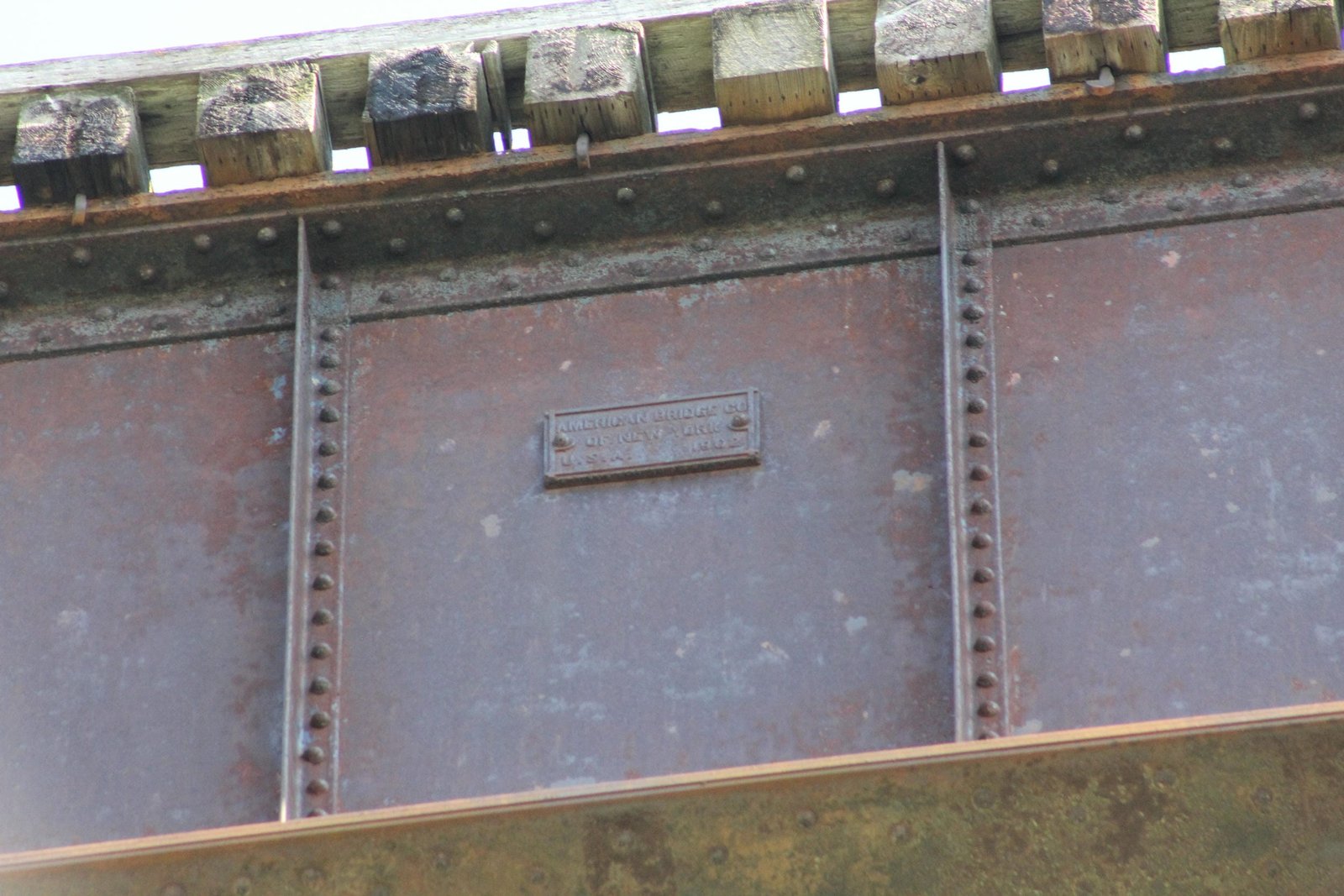
| Superstructure Contractor | American Bridge Company of New York (Various Shops) |
| Substructure Contractor | Bates & Rogers Construction Company of Chicago, Illinois |
| Erection Contractor | Kelly-Atkinson Construction Company of Chicago, Illinois |
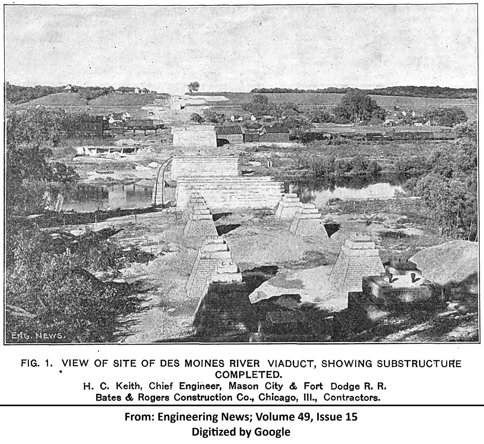
| Design Engineer | H.C. Keith |
| Length | 2582 Feet Total, 219 Foot Main Spans |
| Width | 1 Track |
| Height Above Ground | 138 Feet |
| Superstructure Design | Baltimore Deck Truss and Deck Plate Girder |
| Substructure Design | Steel Tower and Stone Masonry |
| Date Built | Started 1901; Completed 1903 |
| Traffic Count | 1 Train/Day (Estimated) |
| Current Status | In Use |
| Chicago Great Western Railway Bridge Number | C373.60 (Old #D-102) |
| Union Pacific Railroad Bridge Number | 6.31 |
| Significance | National Significance |
| Documentation Date | 7/22/2012; 3/26/2013; 4/17/2017 |
In 1886, the Mason City & Fort Dodge Railroad (MC&FD) constructed 73 miles of new railroad, extending from Mason City, Iowa to Fort Dodge, Iowa. In 1901, the MC&FD was leased by the Chicago Great Western Railway (CGW). Between 1902 and 1903, the MC&FD constructed 133 miles of new railroad, extending from Fort Dodge, Iowa to Council Bluffs, Iowa. The CGW would be reorganized as the Chicago Great Western Railroad in 1909, and maintained a lease of the MC&FD property. The CGW had acquired and constructed a modest railroad network throughout Illinois, Iowa, Minnesota and Missouri; connecting major cities in these states. The CGW was one of the smaller railroads in the area, and was late to develop lines. As a result, the railroad never saw the fortunes of other railroads in the area. This line served as a principal mainline for the CGW, serving agricultural industries and providing a connection to terminals at Omaha, Nebraska. In the early 20th Century, the CGW was often surviving on razor-thin profit margins. In 1940, the CGW entered bankruptcy, and was again reorganized as the Chicago Great Western Railway. At this time, the MC&FD was formally merged into the CGW. After the bankruptcy, the CGW became an innovative railroad, pioneering intermodal service and becoming one of the first railroads to completely switch to diesel locomotives. A capital improvement program was launched in 1949, which sought to rebuild and rehabilitate deteriorated infrastructure.
In 1953, the Chicago, Rock Island & Pacific Railroad (Rock Island) began using a segment between McClelland, Iowa and Council Bluffs. In 1968, the CGW was purchased by the Chicago & North Western Railway (C&NW). The C&NW already owned a better constructed route serving Council Bluffs, and much of this line became excess for the C&NW. In 1971, a section of the line between Harlan and Council Bluffs was abandoned, and the McClelland to Council Bluffs segment sold to the Rock Island. An additional segment between Somers and Carroll was abandoned in 1977, followed by a section between Manning and Harlan in 1981 and a section between Carroll and Manning in 1983. After the Rock Island went bankrupt in 1980, the McClelland to Council Bluffs segment became part of the Iowa Interstate Railroad (IAIS). In 1995, the C&NW was purchased by Union Pacific Railroad (UP). UP abandoned a section of the line between Thornton and Belmond in 2000, followed by a section between Mason City and Thornton in 2007 and a section between Roelyn and Somers in 2008. Today, UP operates the Fort Dodge Subdivision between Belmond and Roelyn and IAIS operates a short segment of the Council Bluffs Subdivision between McClelland and Council Blufffs. The segment between Mason City and Belmond was acquired for trail use, and portions of the right-of-way have been reused as part of the Prairie Land Trail. The remainder of the line has largely reverted to adjacent landowners, and has been converted to farm fields.
View historic articles discussing the construction of this bridge (digitized by Google)
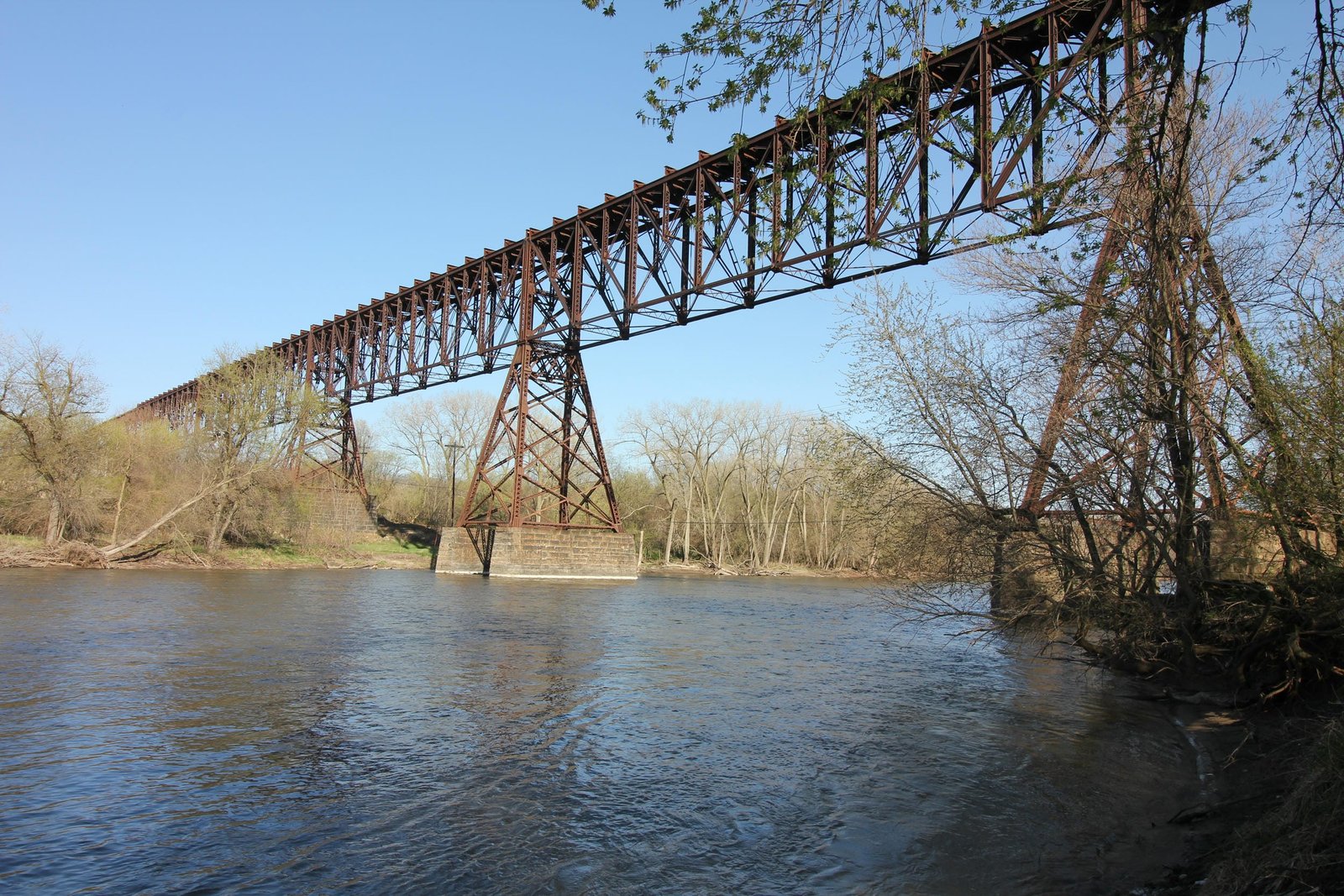
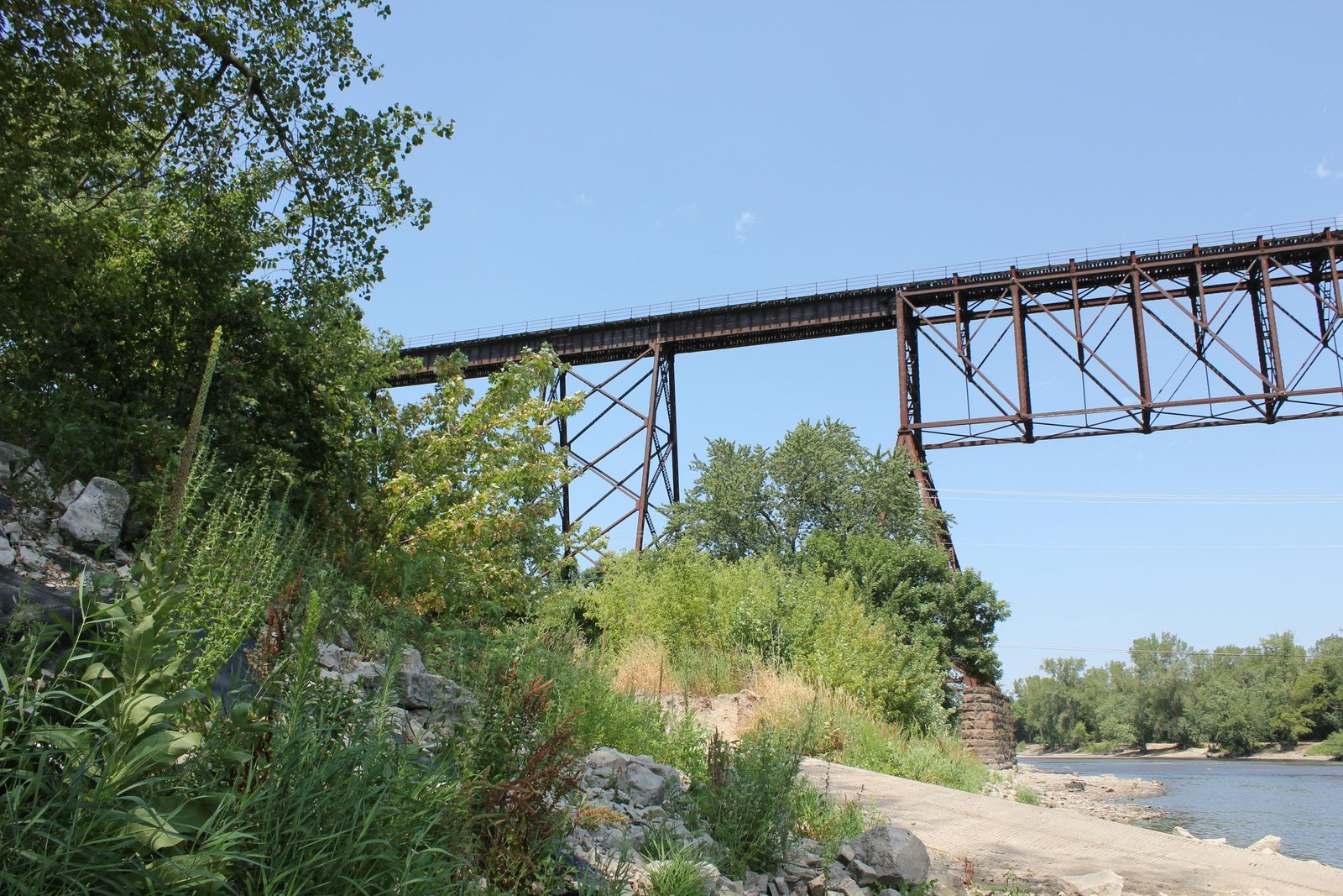
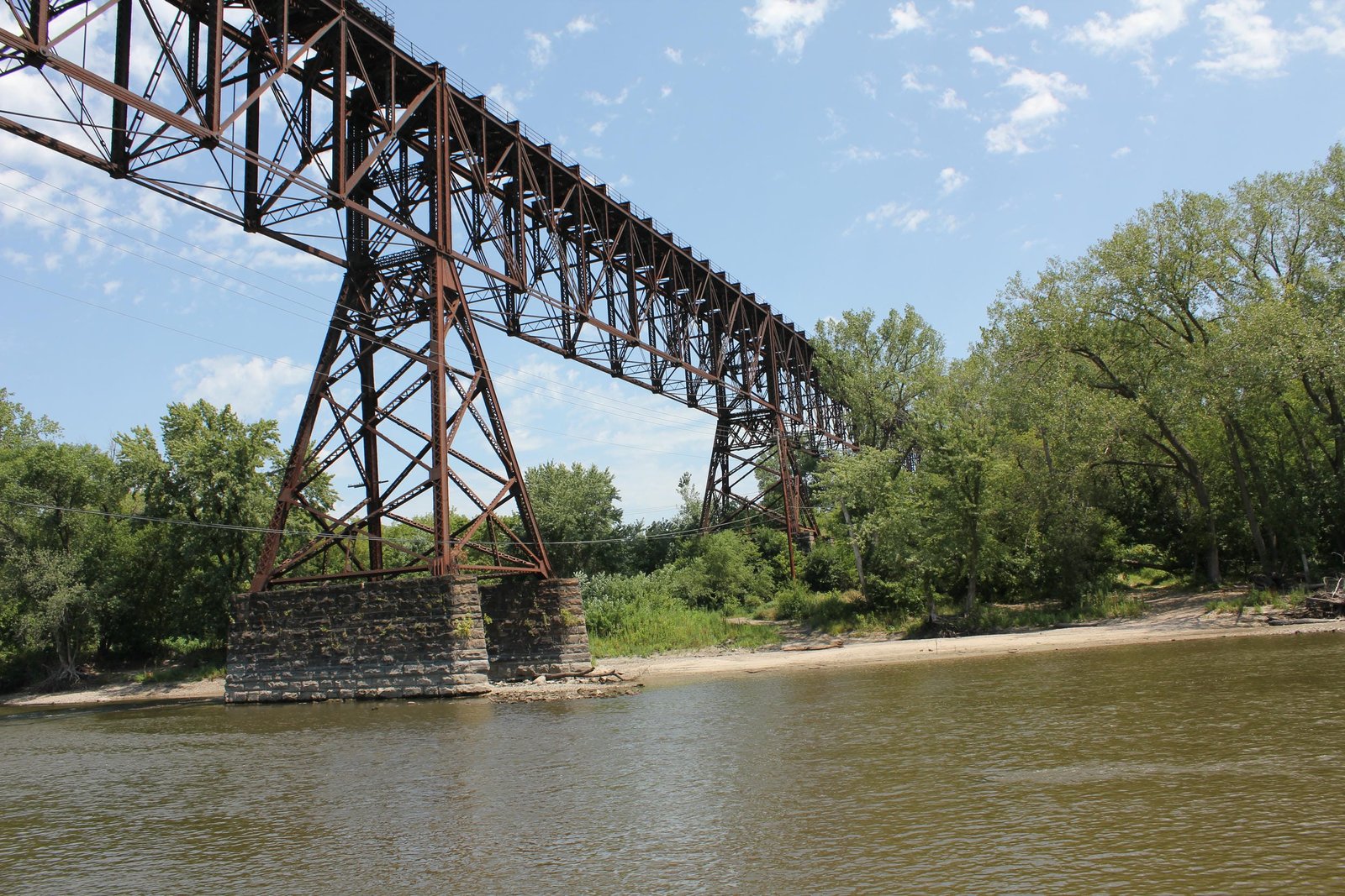
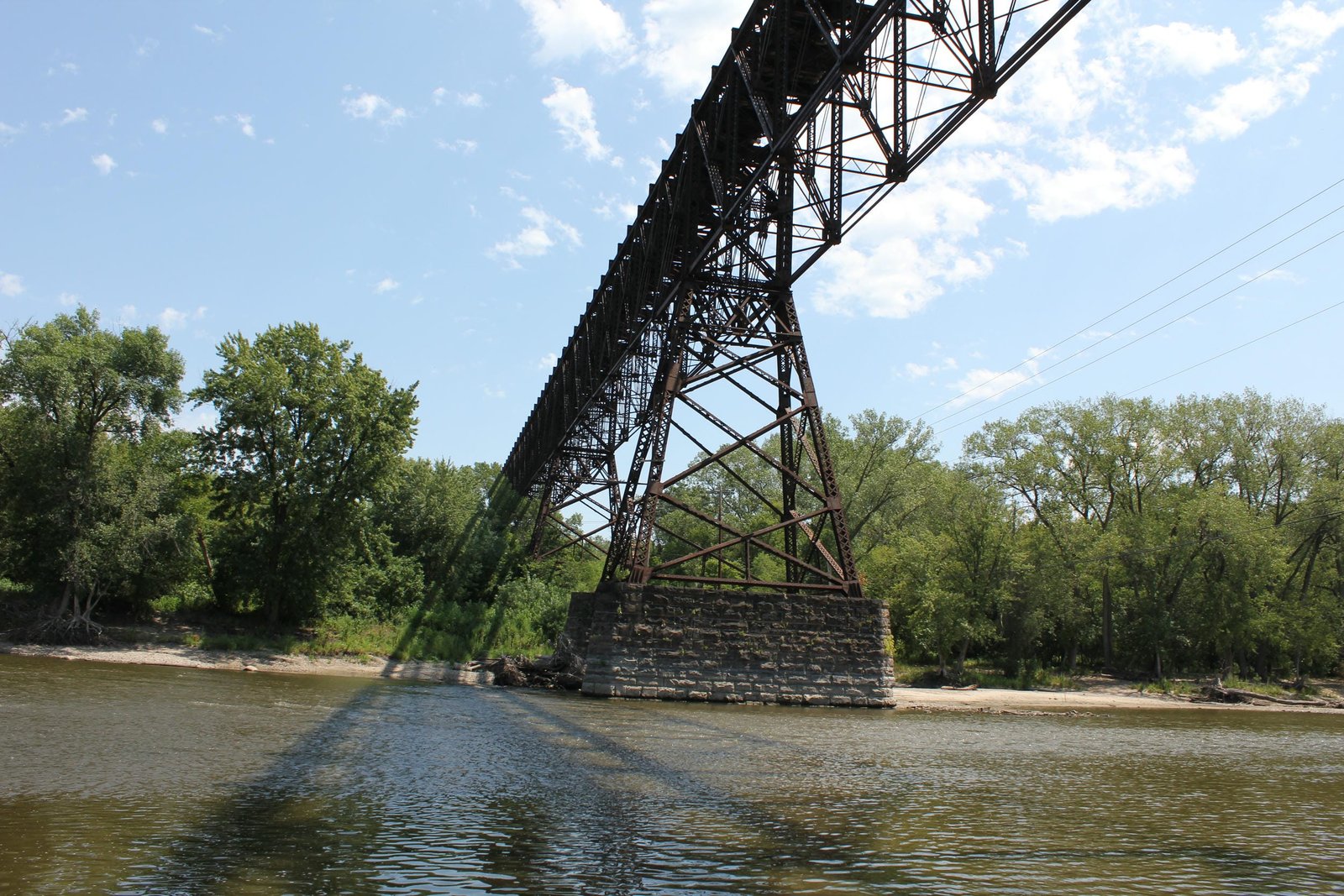
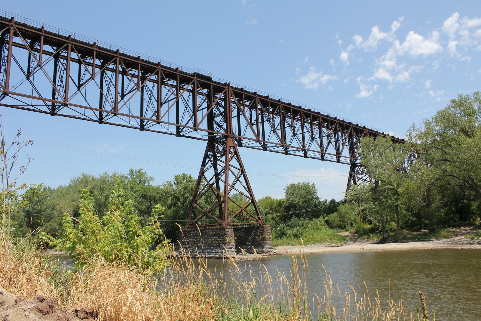
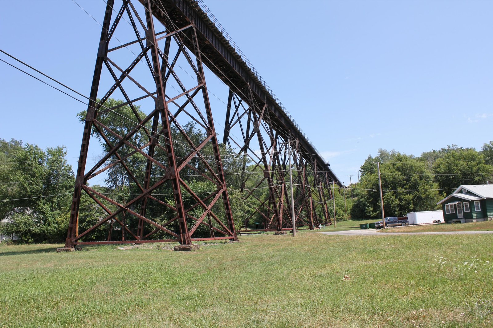
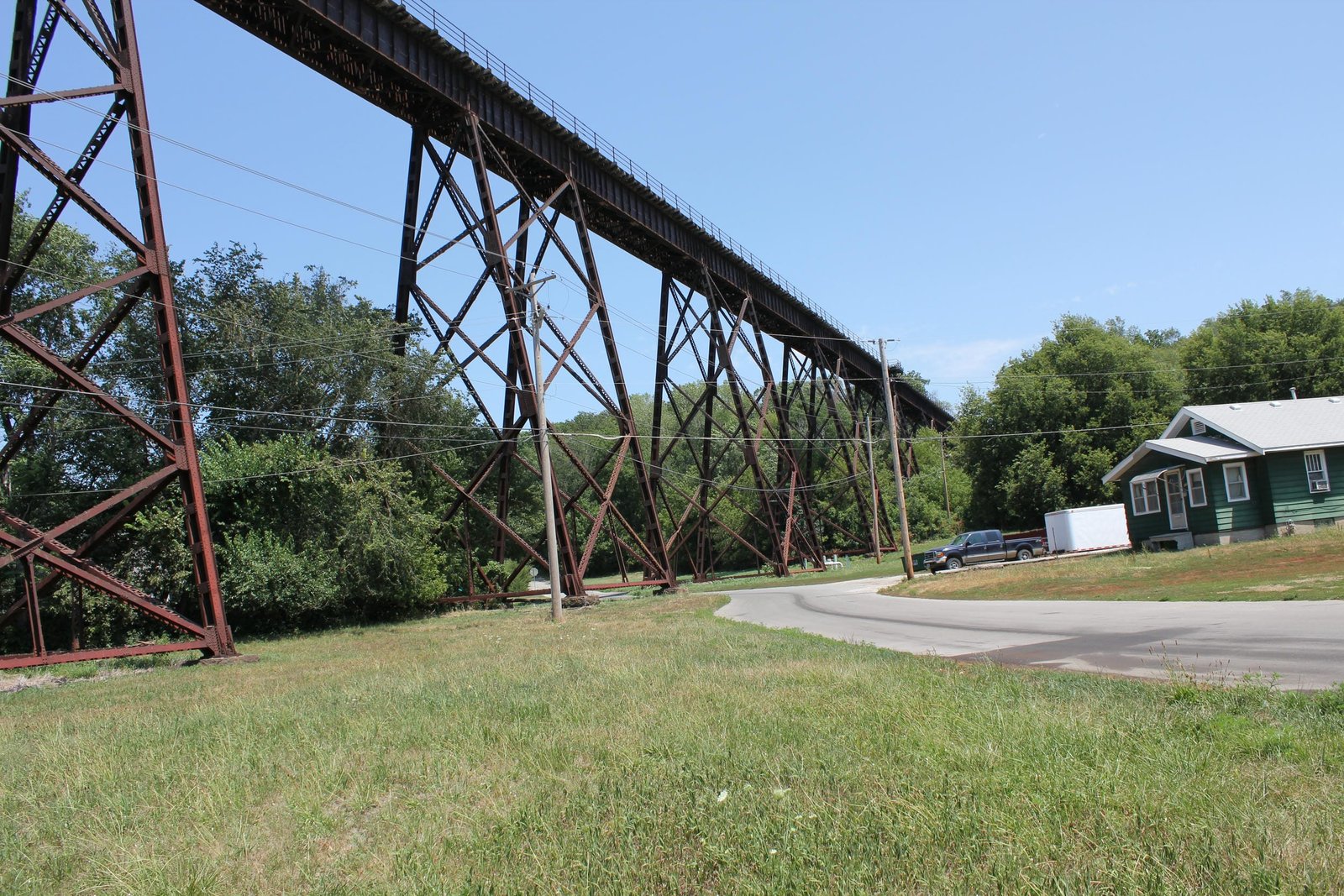
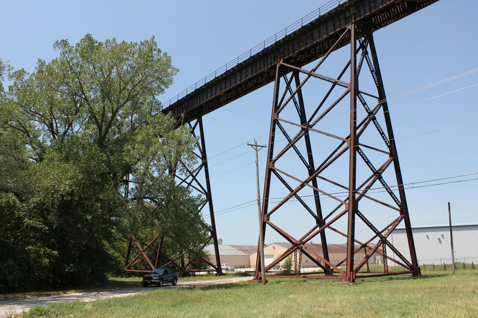
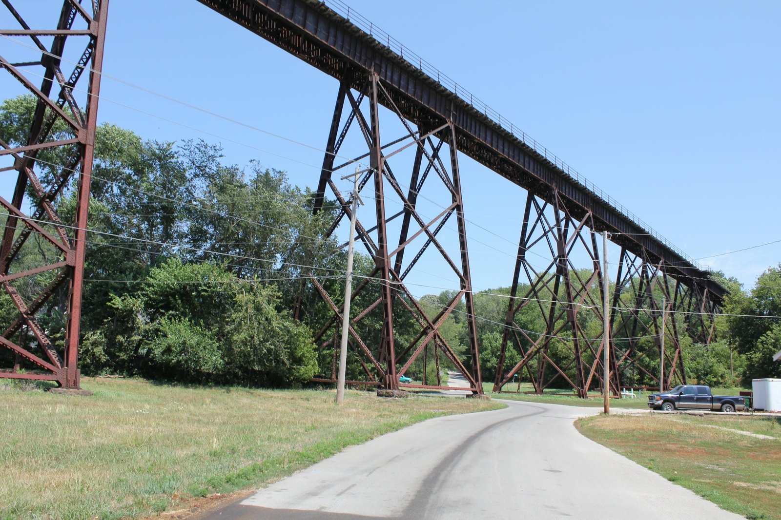
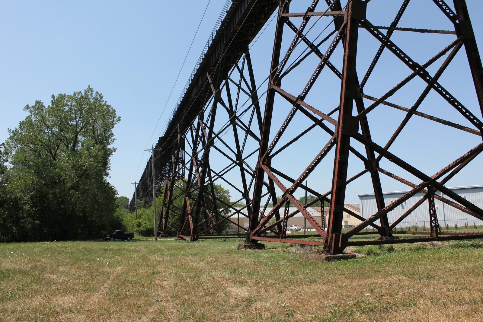
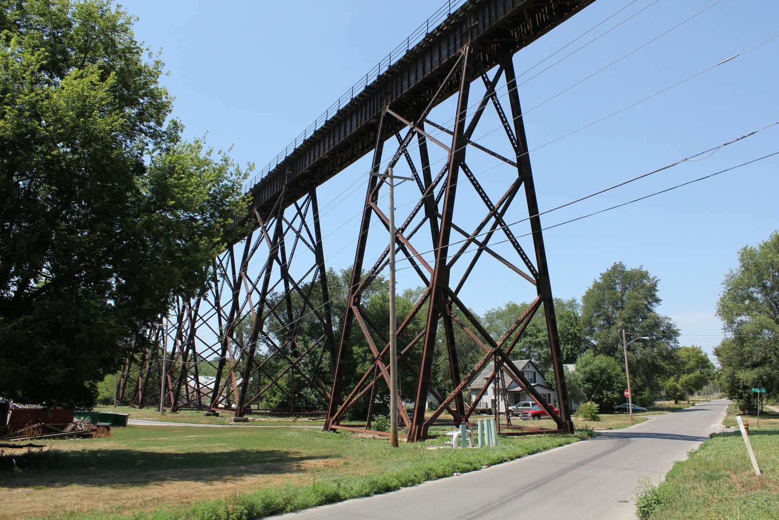
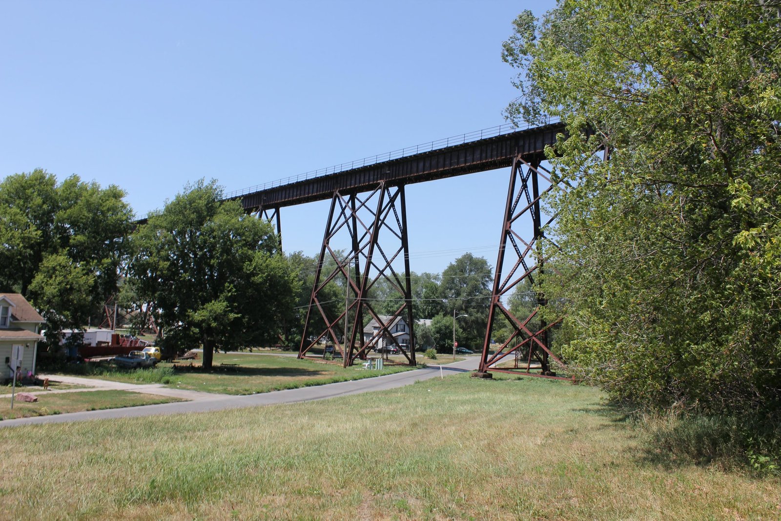
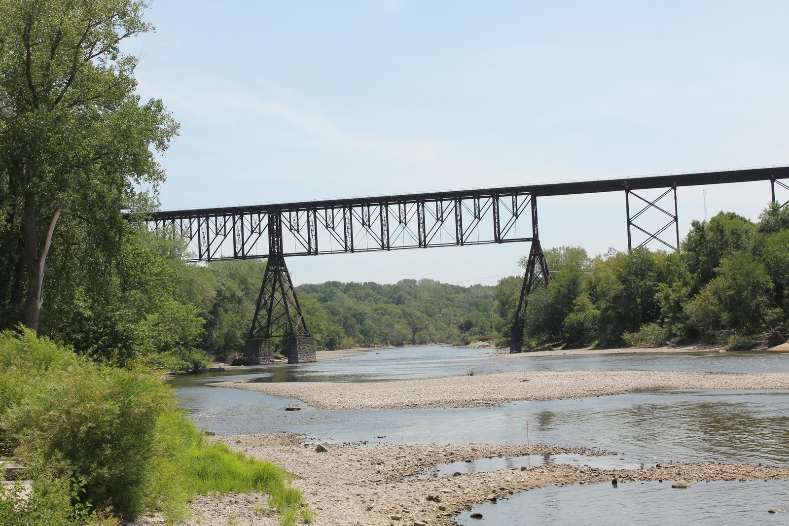
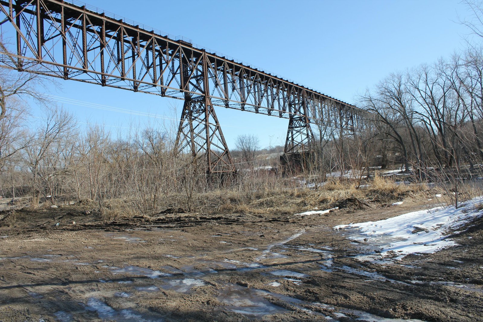
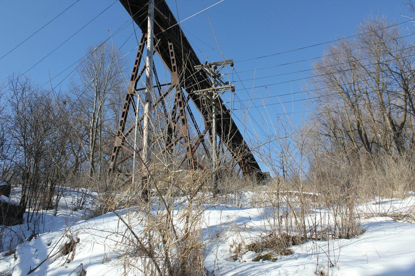
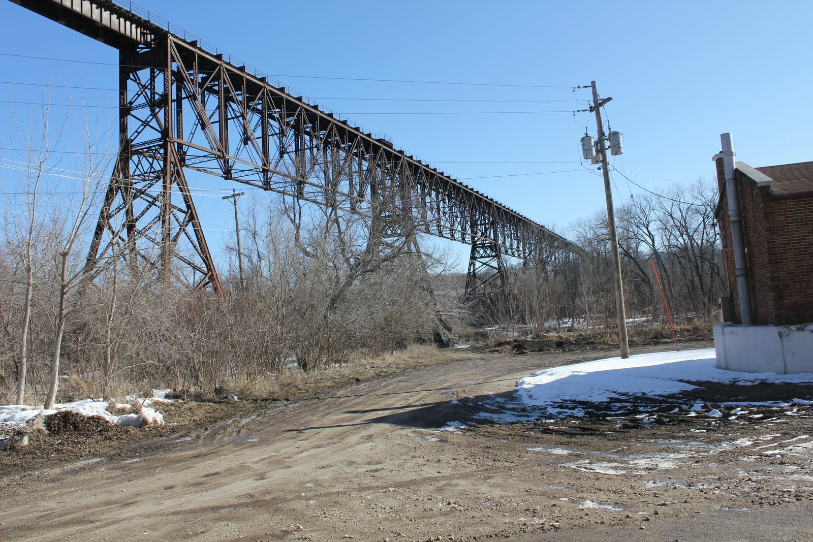
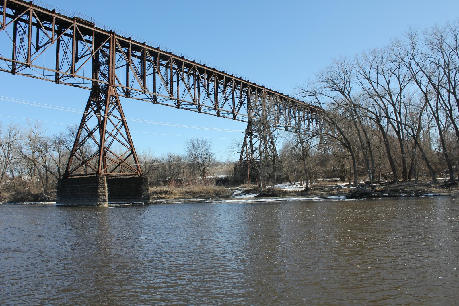
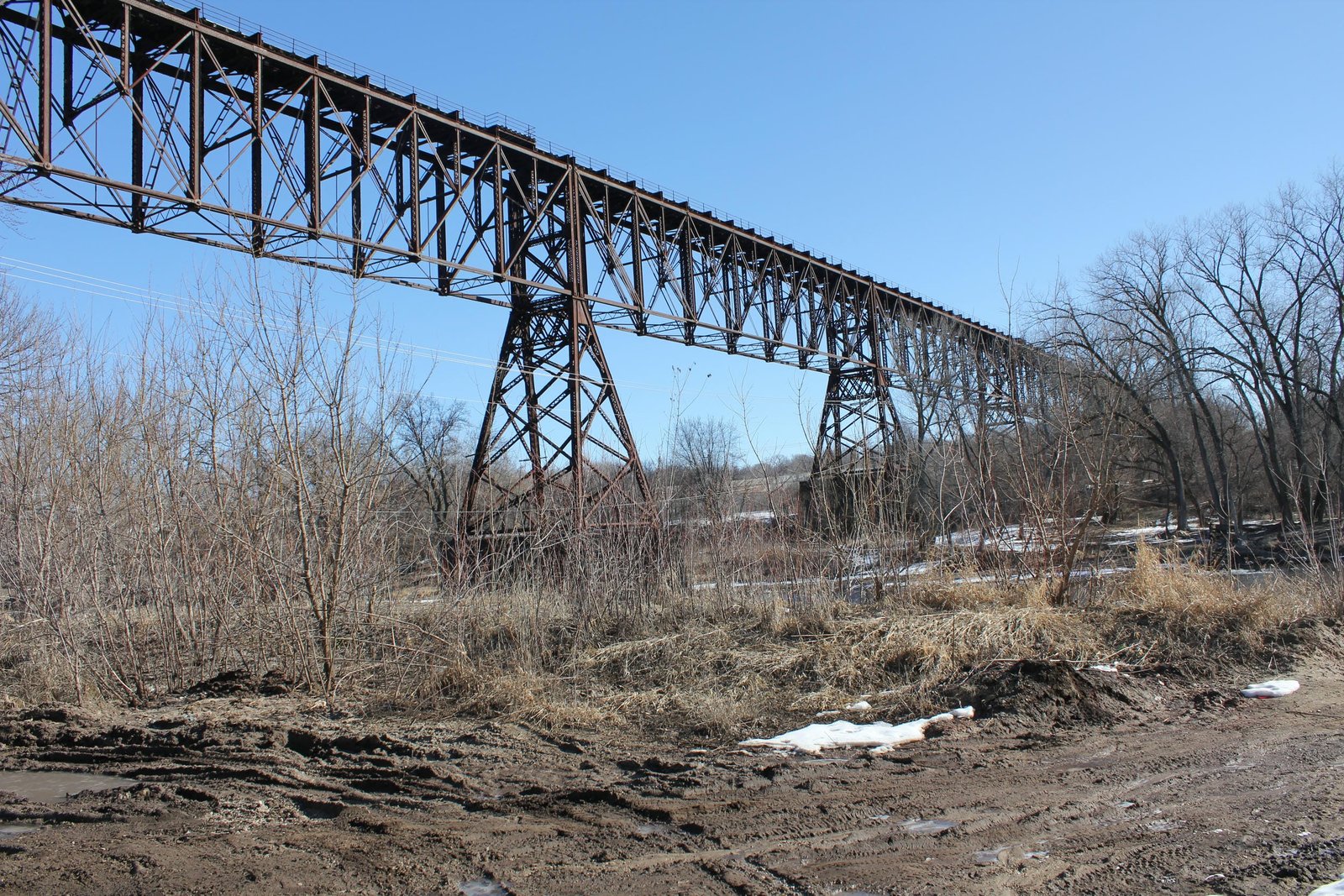
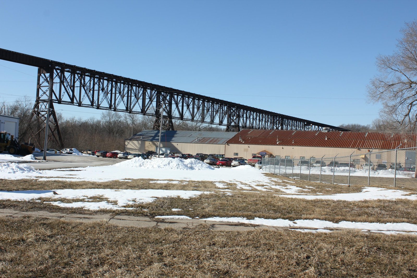
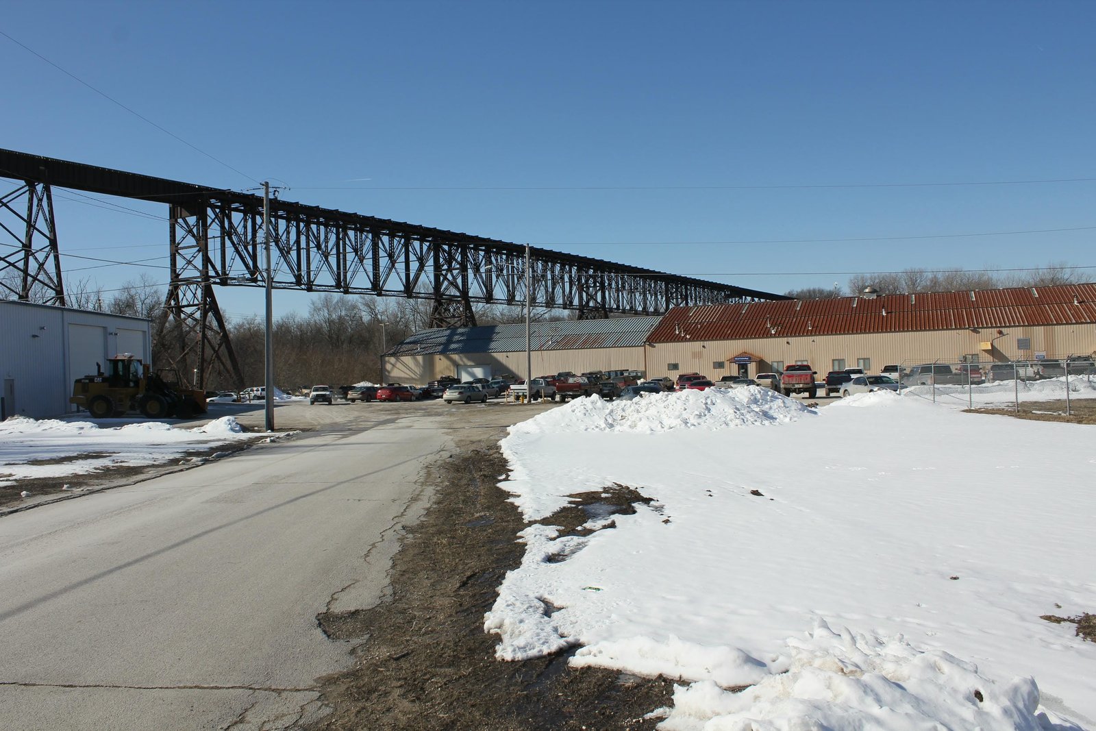
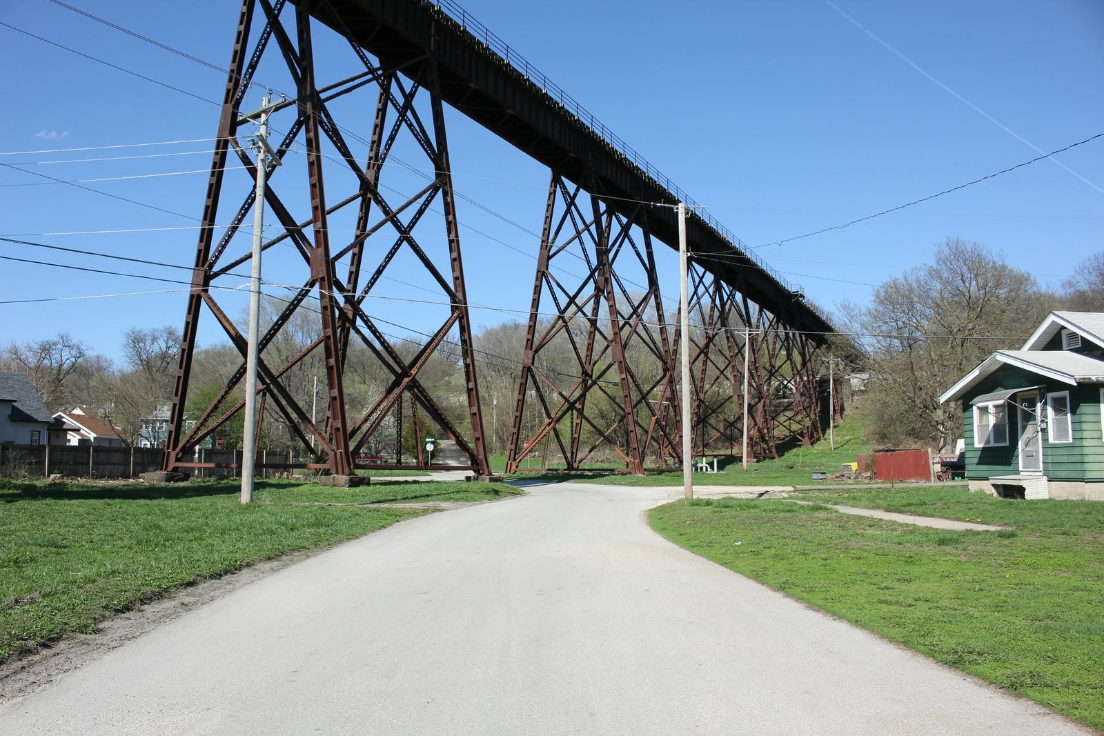
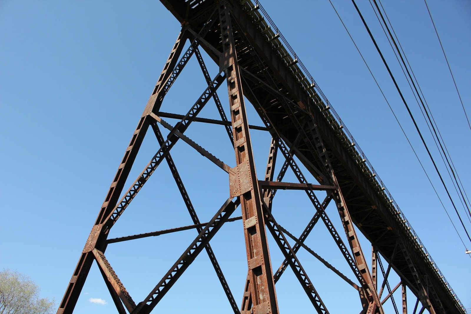
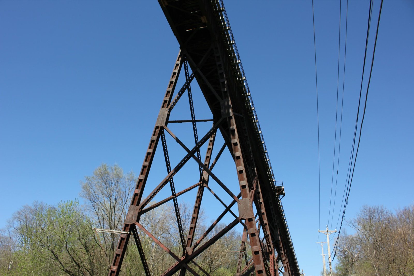
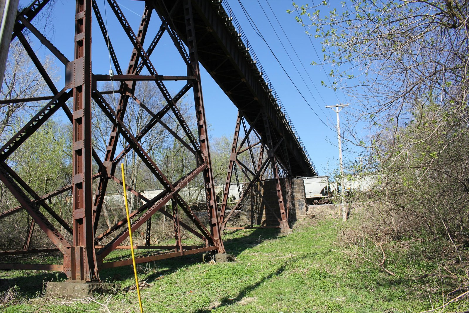
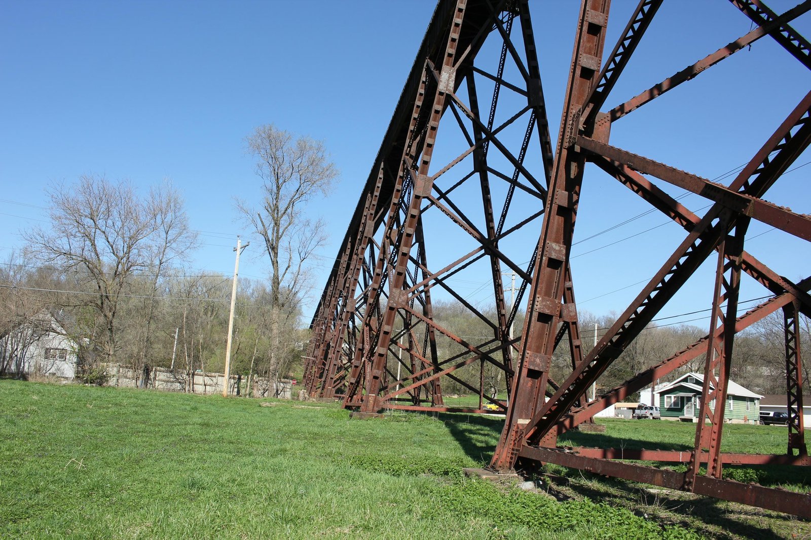
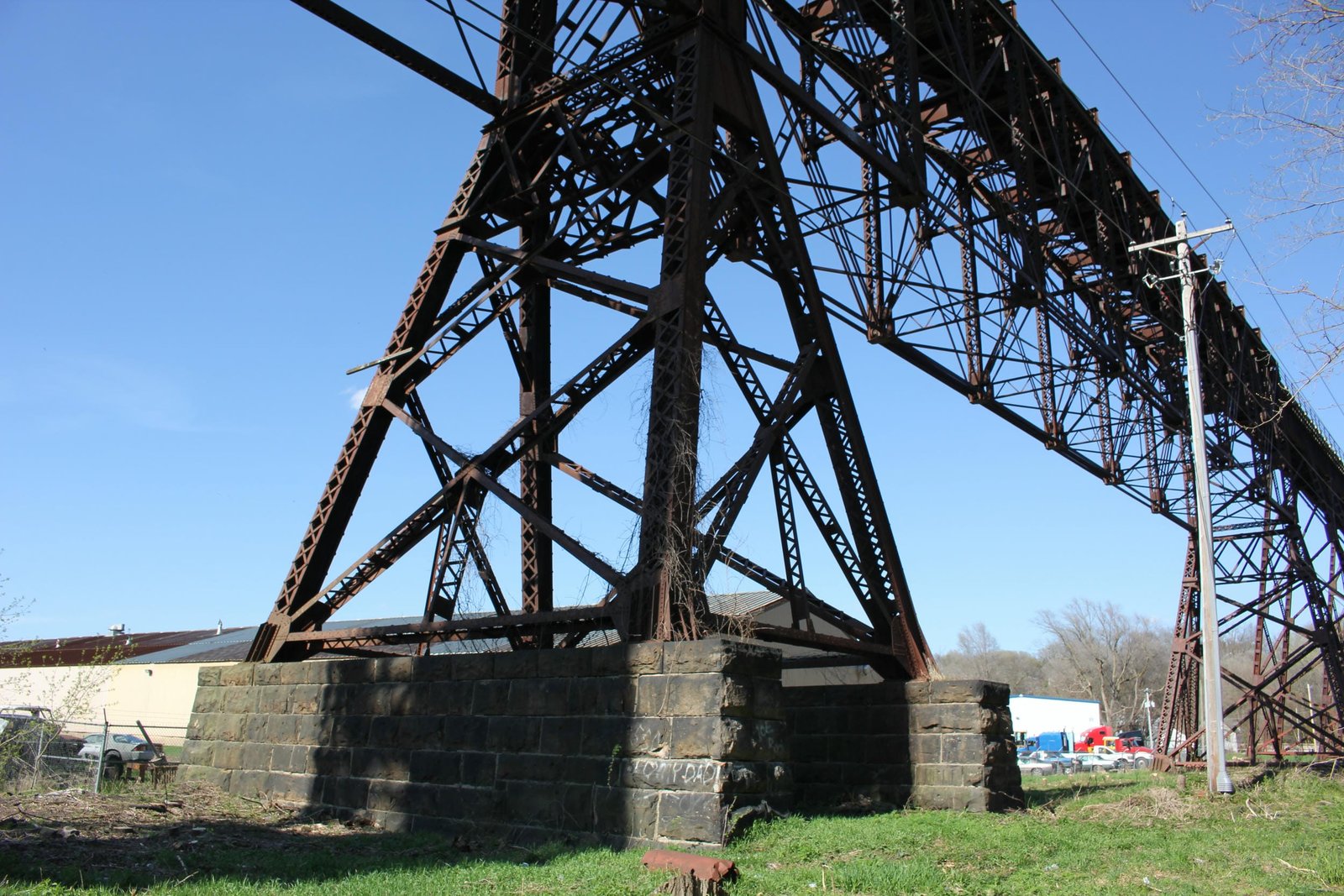
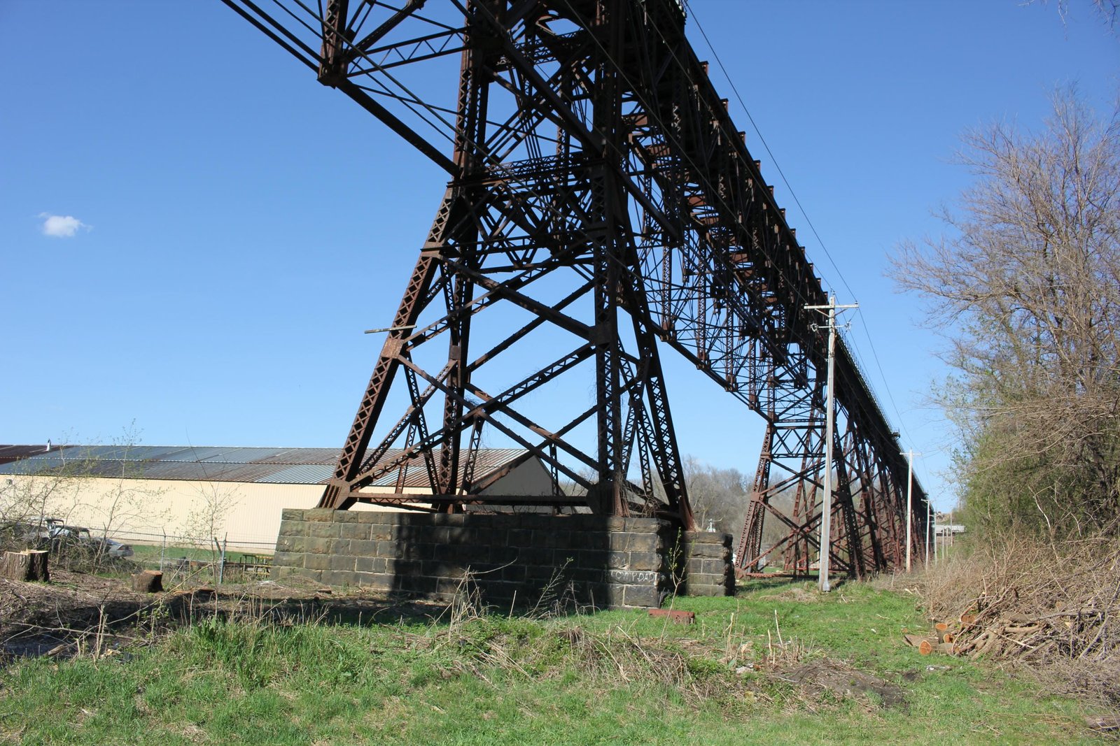
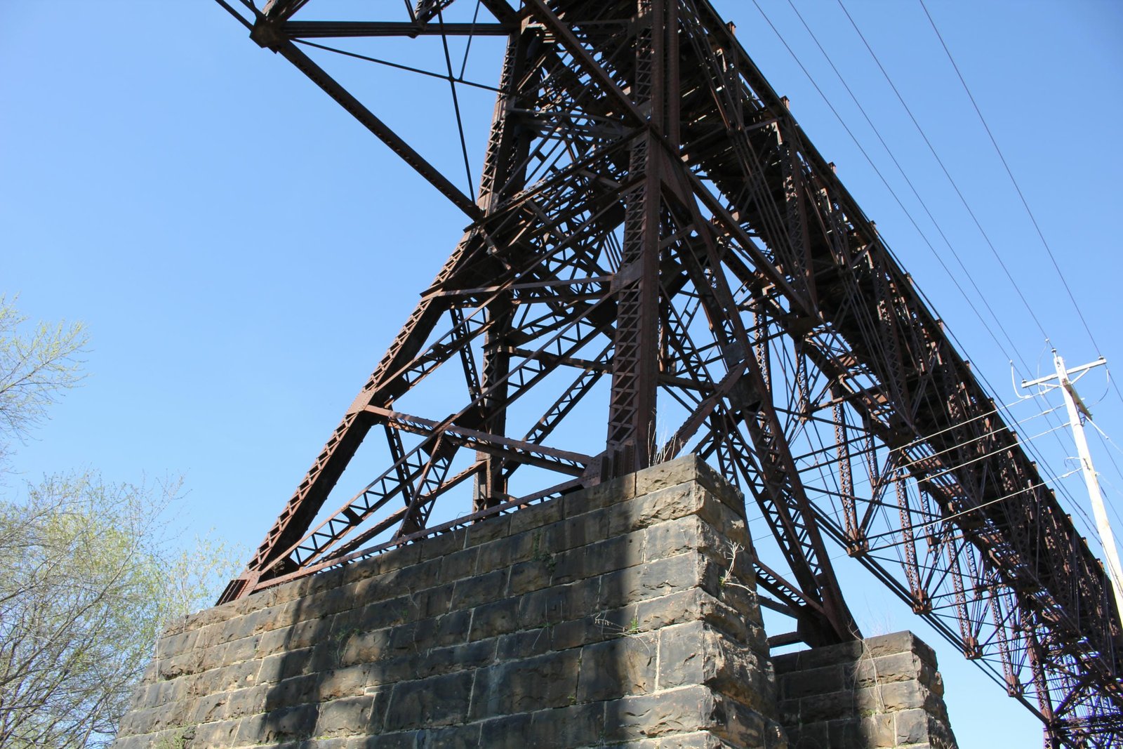
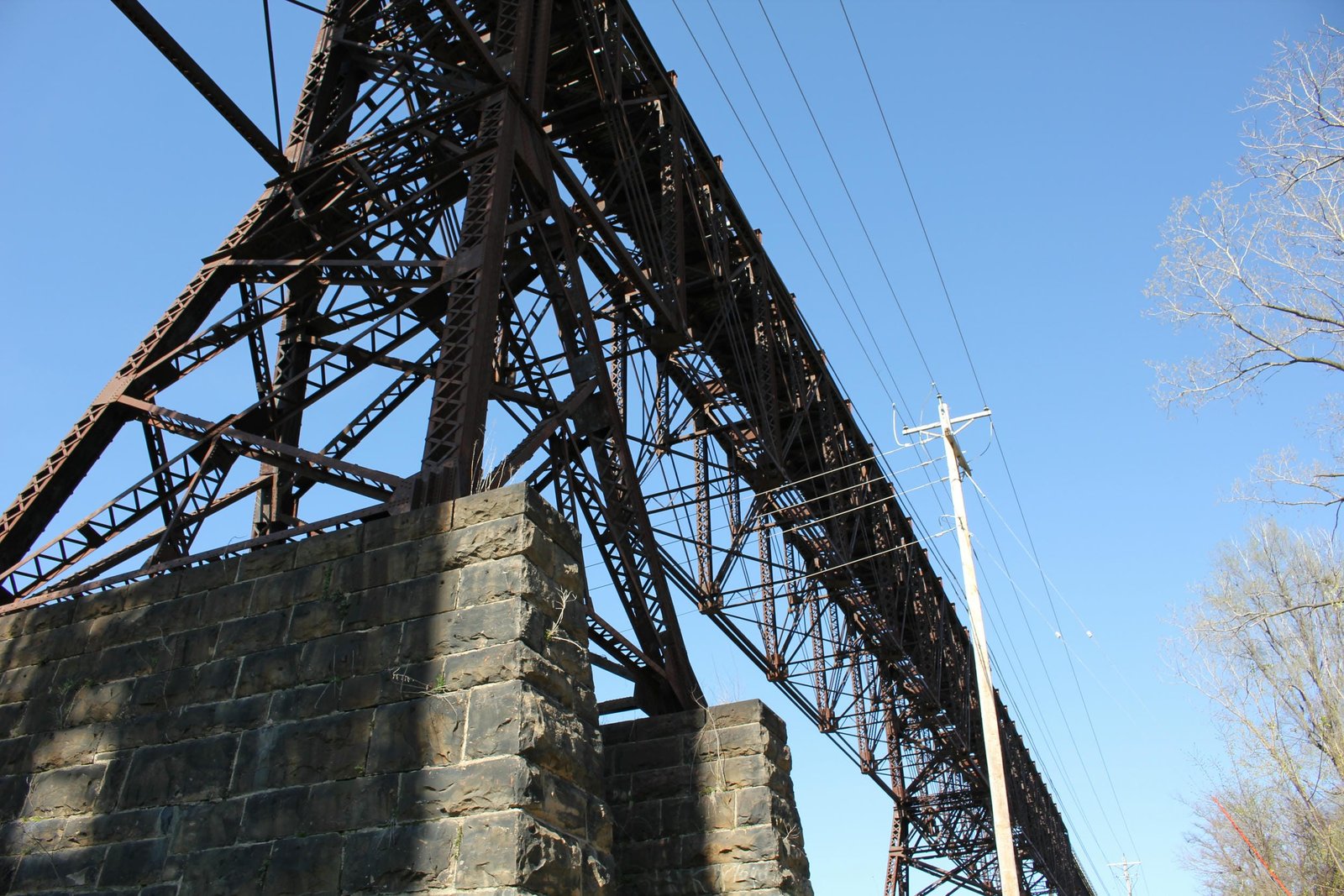
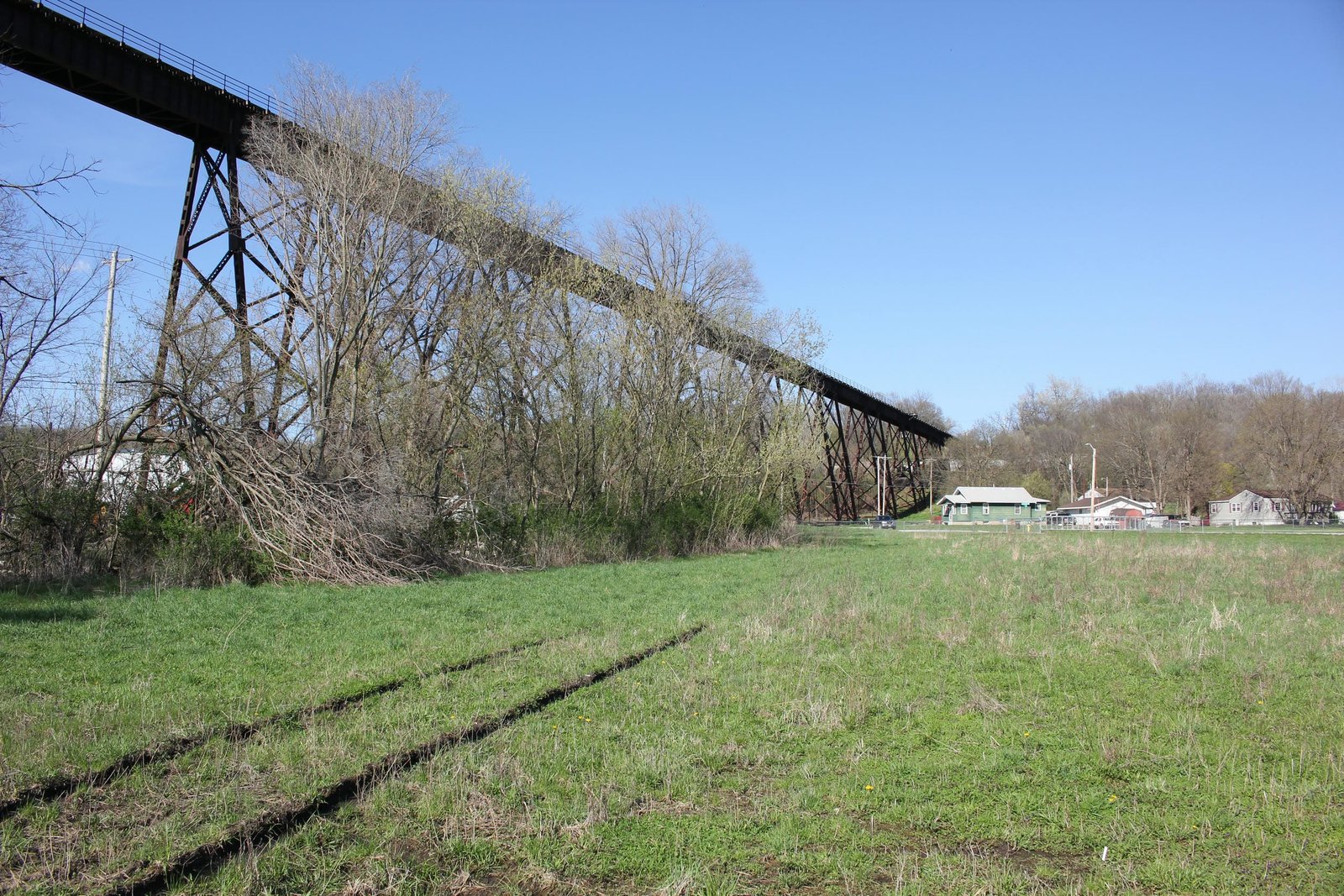
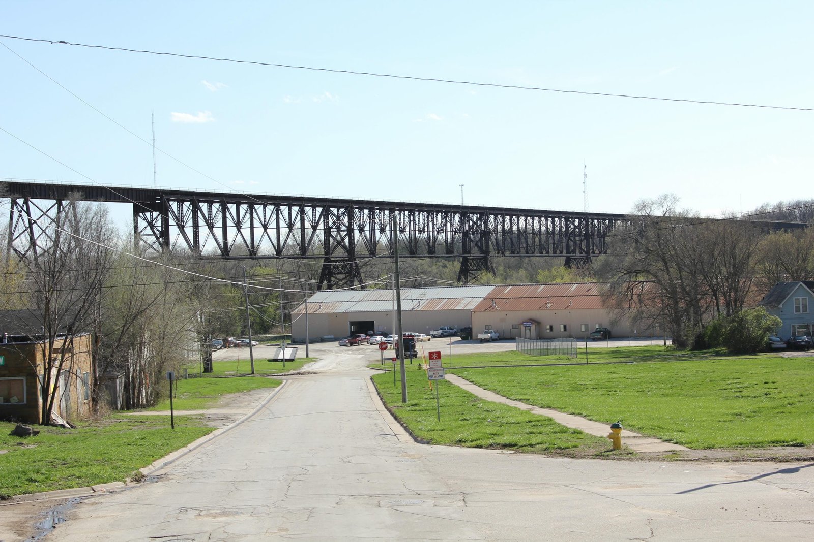
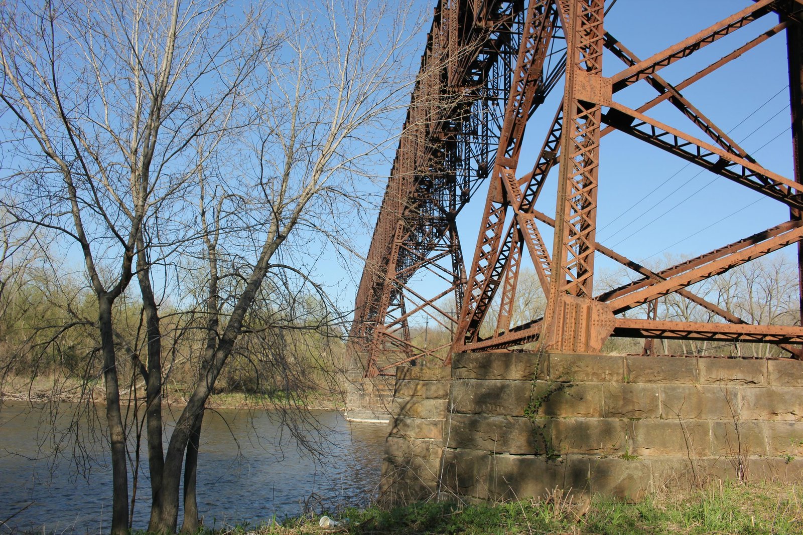
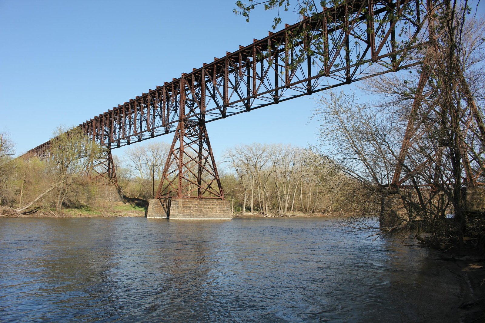
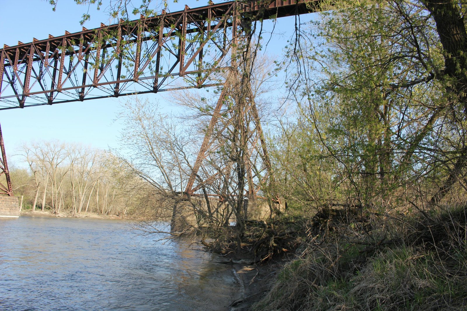
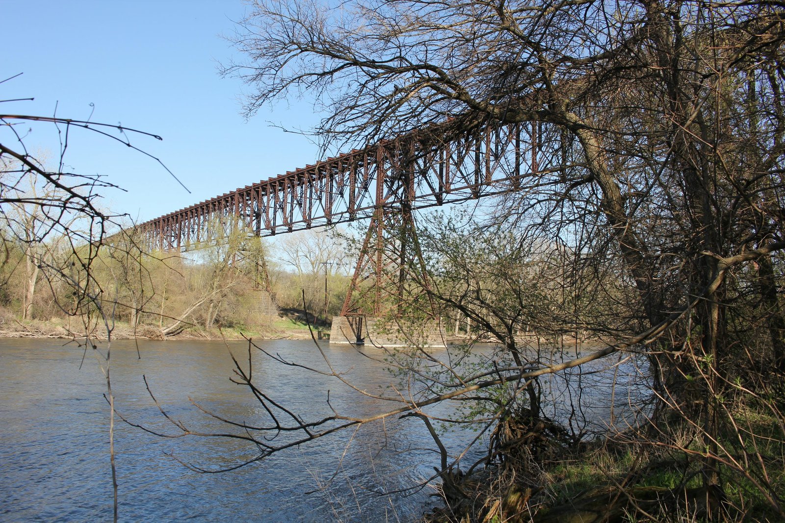
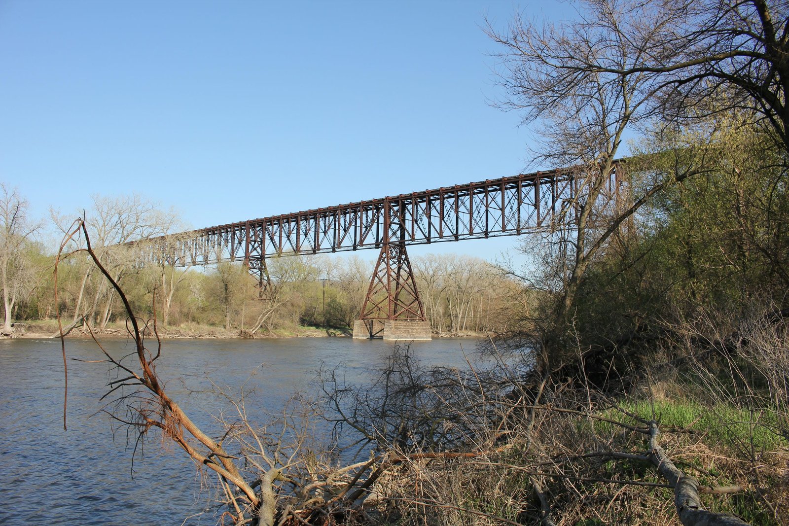
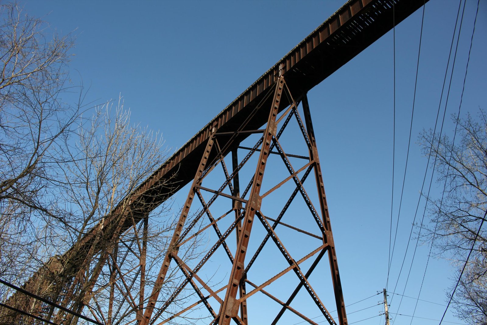
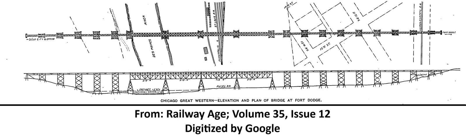
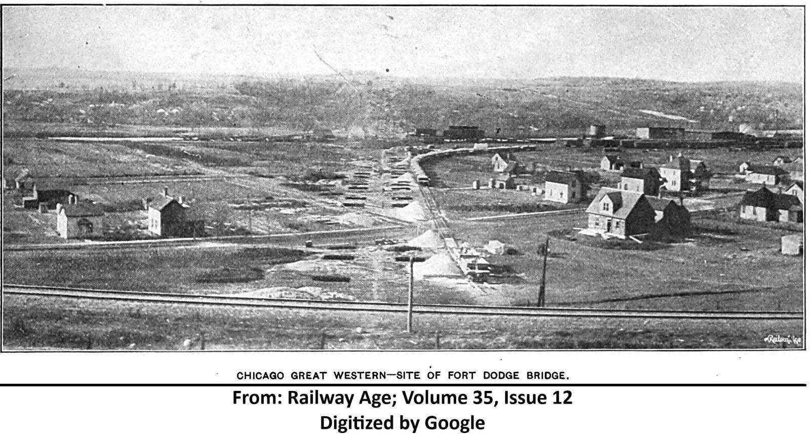
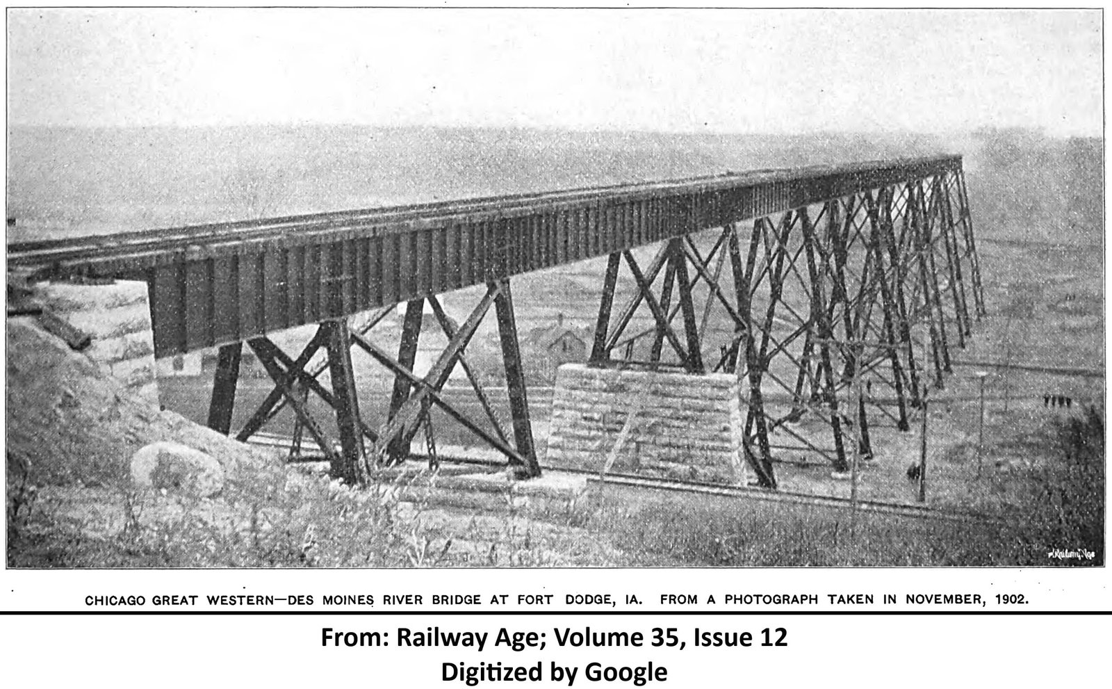
Located in Fort Dodge, this massive deck truss and deck girder viaduct carries a former Chicago Great Western Railway mainline high above the Des Moines River, Canadian National Railway and several city streets. At this location, the Des Moines River runs through a deep valley, with the adjacent lands approximately 160 feet above the river and the valley approximately 7,000 feet wide. As the CGW planned a new line, the Des Moines River created a formidable obstacle. Since the existing MC&FD line extered Fort Dodge at the top of the bluff, constructing a low level crossing would have required expensive realignments, using existing creek valleys that already were used by other railroads. Instead, the most cost effective solution was to construct a high level bridge, which would allow the line to maintain minimal grades and curvature. In addition, a high level bridge allowed the CGW to cross a single track Illinois Central Railroad mainline and a Minneapolis & St. Louis Railway yard without requiring a separate structure or grade crossing. H.C. Keith, Bridge Engineer of the MC&FD was tasked with designing and overseeing construction of the bridge. Planning for the bridge began in July 1901, including extensive testing of the soil to determine the best design and best tower arrangement. The test methods for determining soil stability are described in the Railway Age article from March 20, 1903; which is included above. It was decided that a deck plate girder viaduct with deck truss main spans would provide the most cost effective structure. Temporary spur tracks were constructed to aid in the delivery of materials to the site. Two spurs were constructed from the M&StL tracks, with one extending east along the viaduct and the other using a temporary trestle across the river to reach the west end.
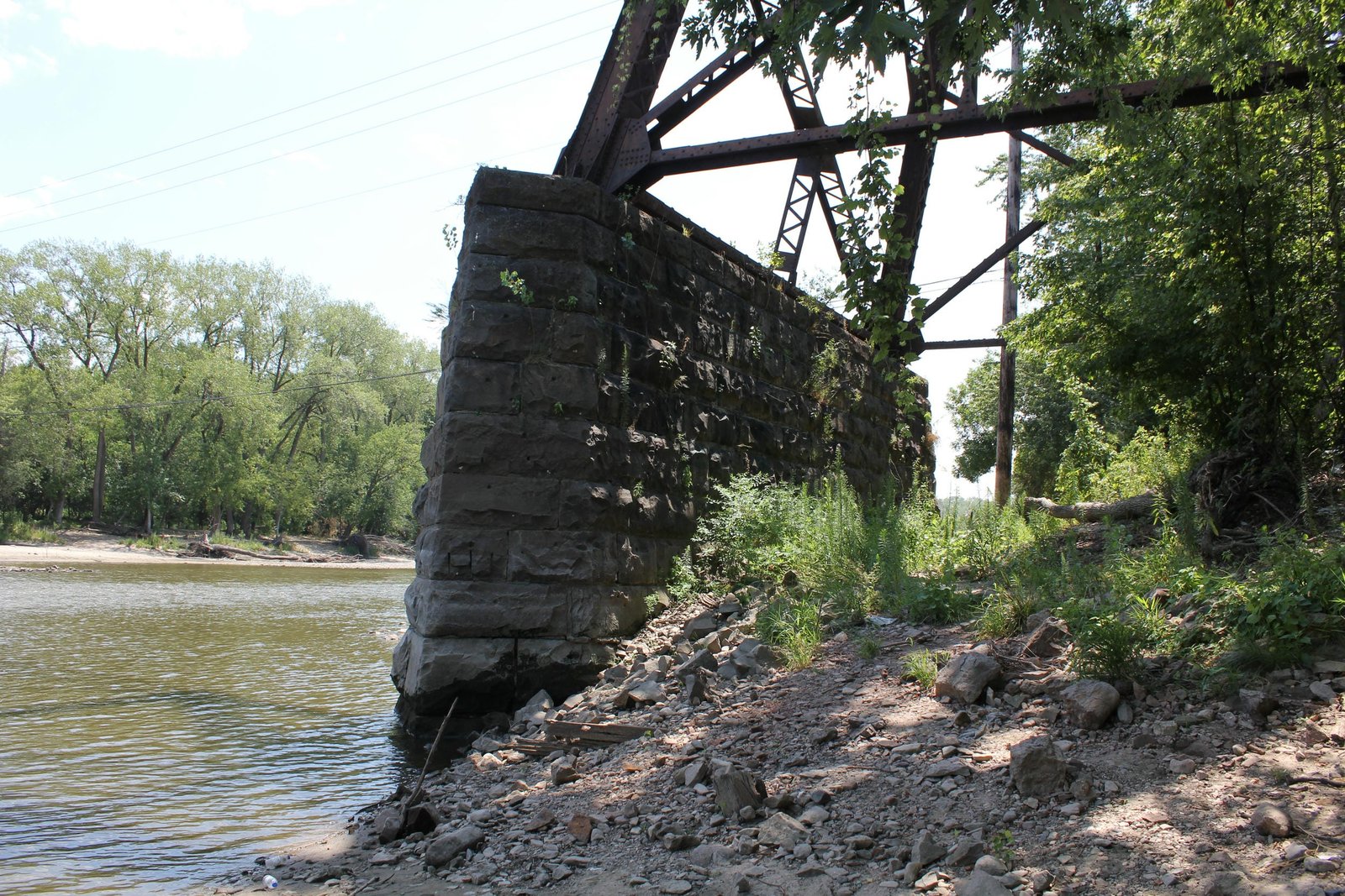
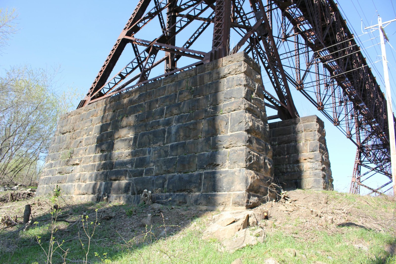
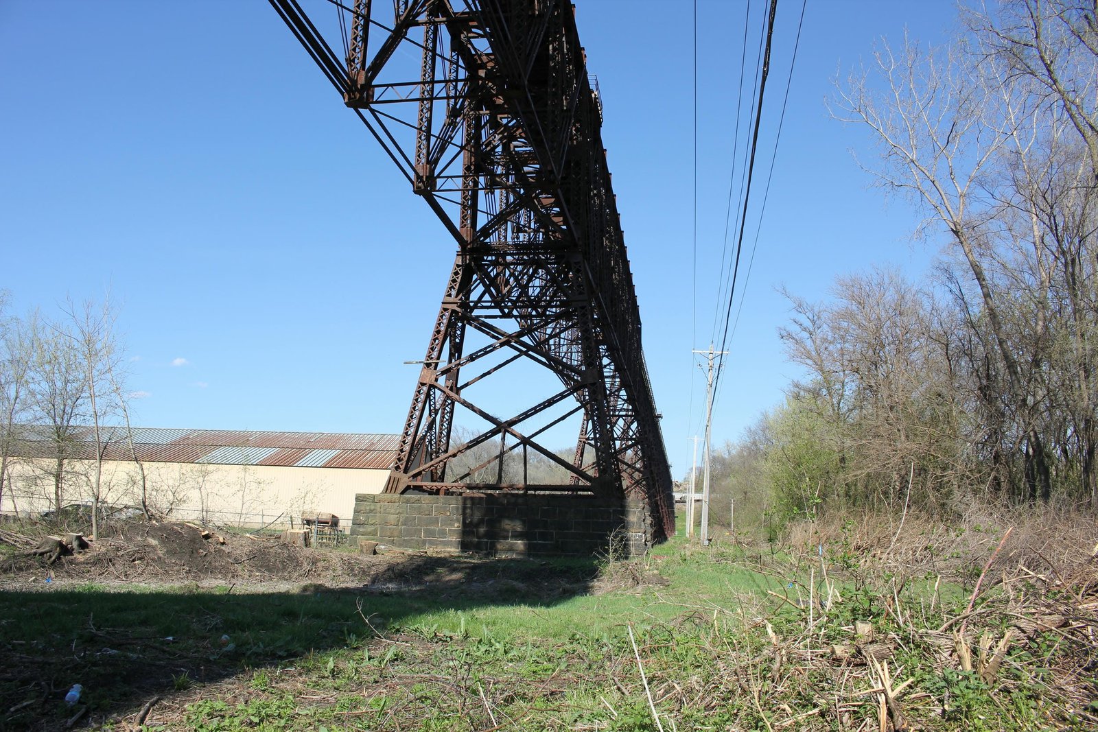
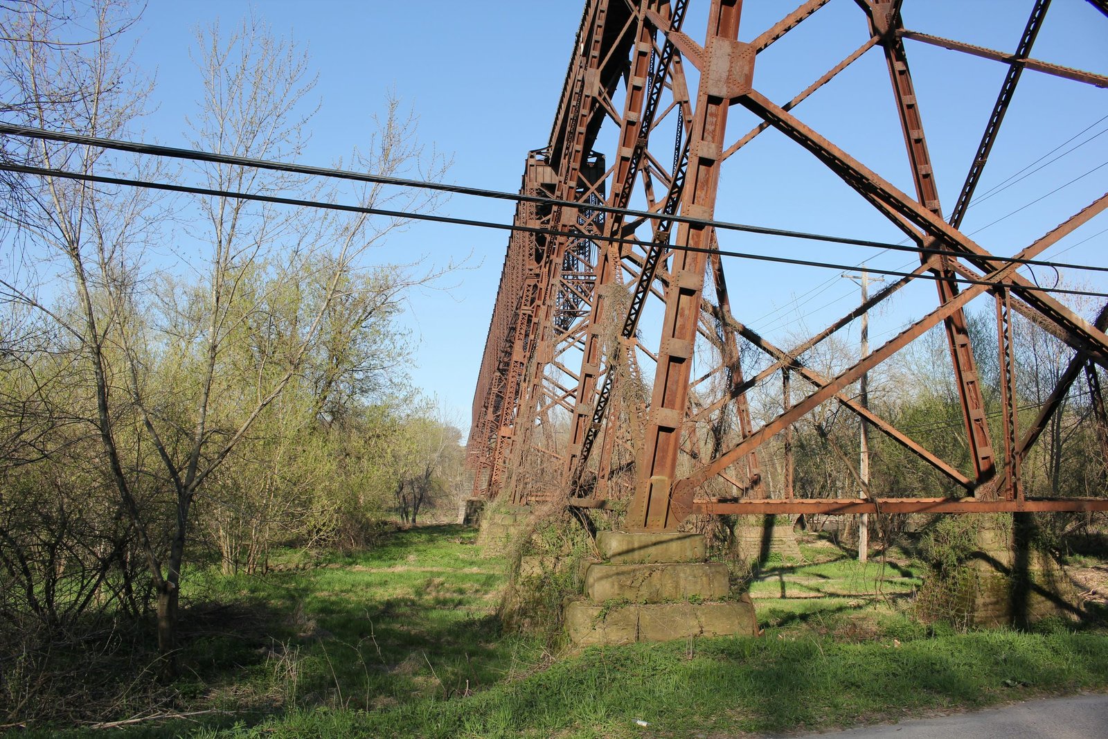
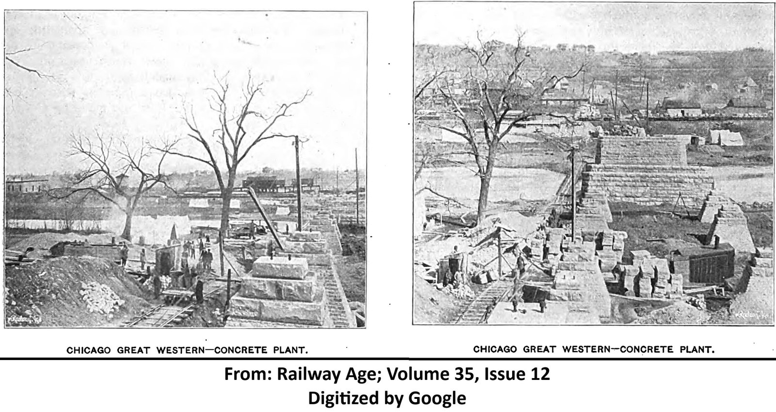
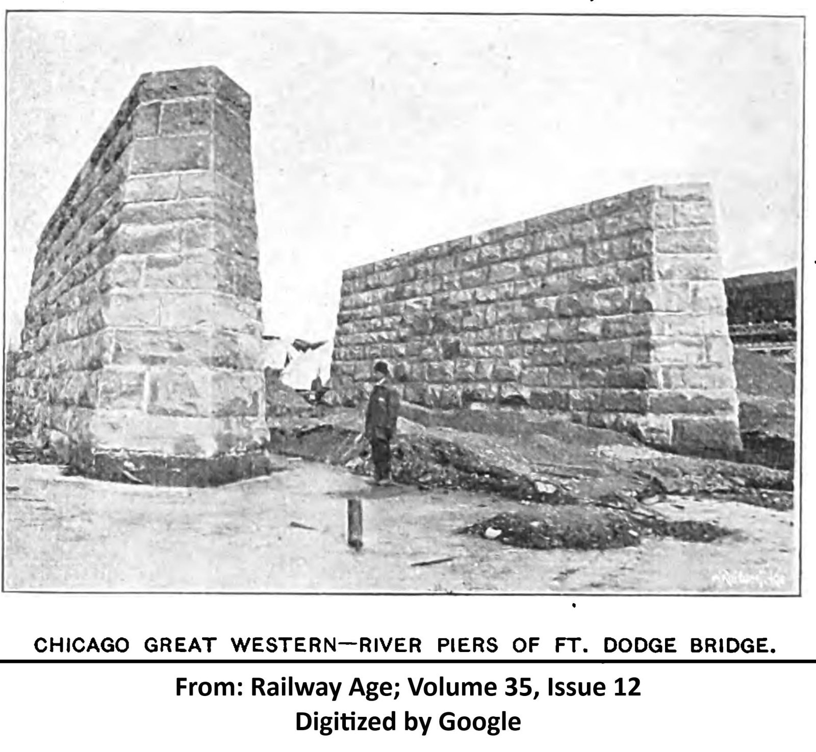
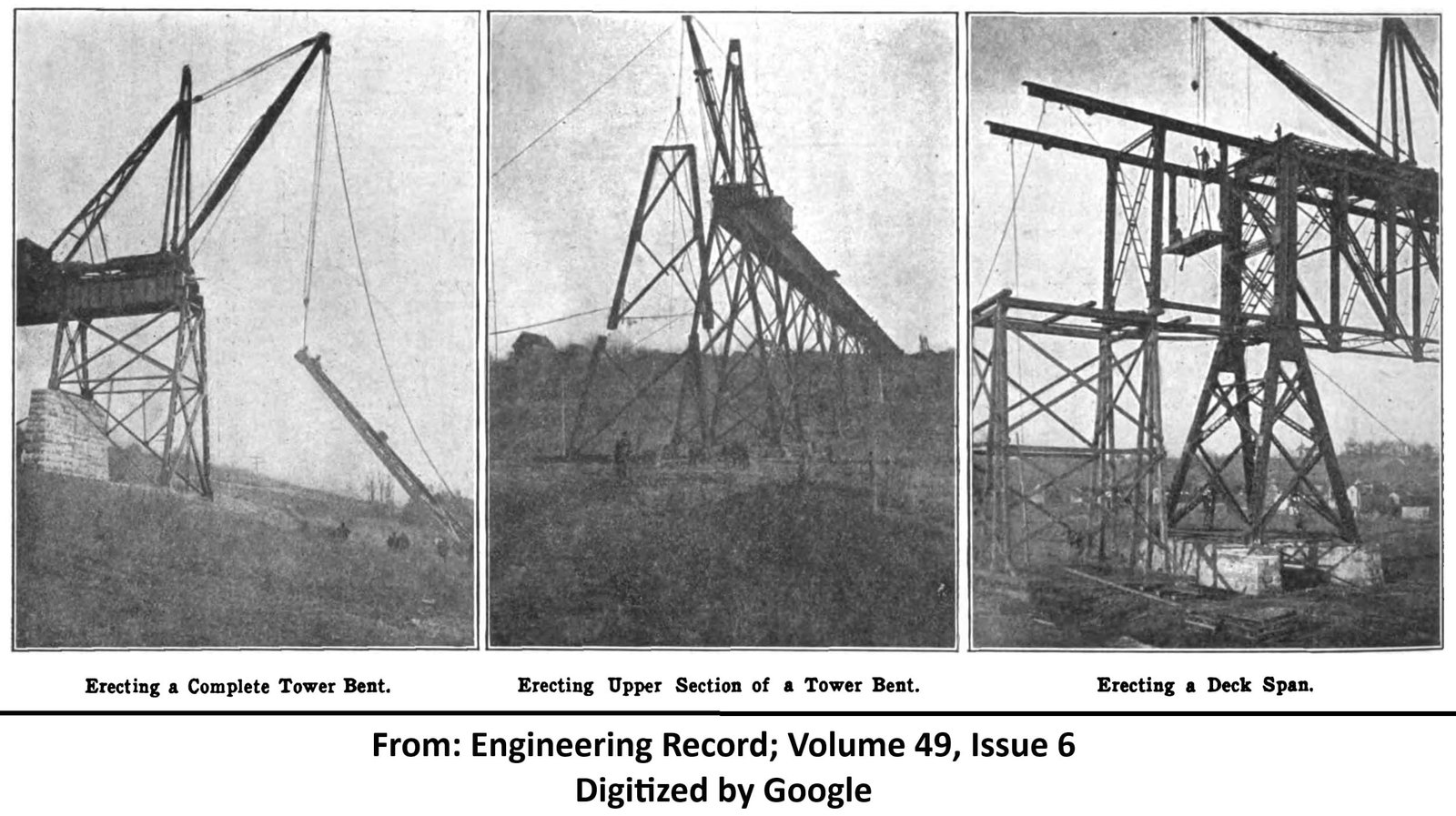
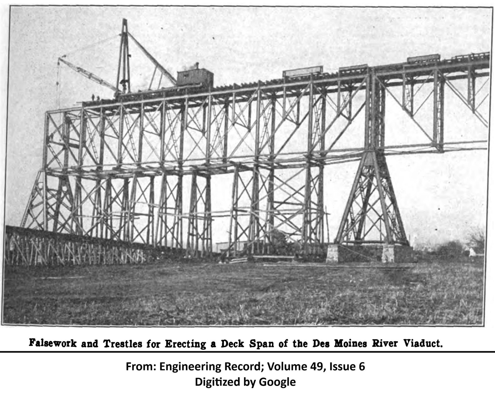
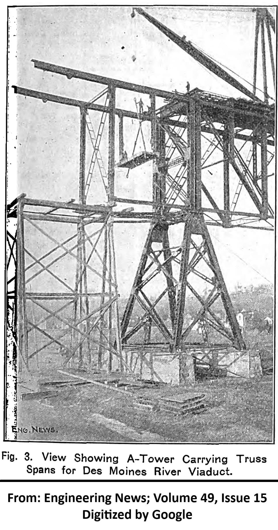
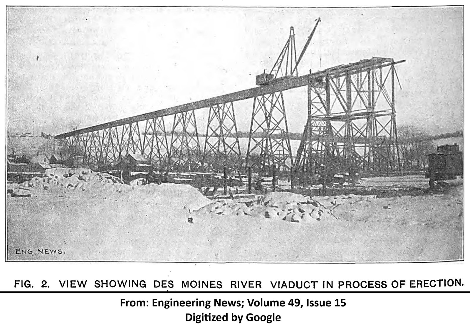
Actual construction of the bridge began in October 1901, when Bates & Rogers Construction Company began construction of the substructure. Stone for the substructures was constructed of Kettle River Sandstone, delivered from Sandstone, Minnesota. This stone was far cheaper than granite or quartzite that could be found in Iowa, and was more suitable for building than the native stone. Work on the substructures continued throughout the remainder of 1901 and was completed in June 1902. Stone for the substructures was laid in concrete, which was mixed using a concrete mixer that was set up on site. No concrete was laid turning times of extreme temperature changes or extreme cold, although work continued through the winter when conditions allowed. After completion of the substructures, material for the superstructure was unloaded at the east end of the viaduct and laid out for approximately half the structure. Erection began on the east end, using a traveler and derrick car. Where the towers were too tall for a single post, posts were spliced together and erection was completed from the ground up. The truss spans were erected using a traveler on the completed portion of the viaduct, and temporary bents were installed underneath the spans to facilitate erecting the bottom chord. Erection of the steel was commenced on October 8, 1902; reaching as far as the third truss span by January 22, 1903. The entire superstructure was in place by March 10, 1903; and the first train crossed the bridge on March 14. American Bridge Company fabricated the superstructure at various shops, while the Kelly-Atkinson Construction Company completed the erection. The shorter tower spans and towers were fabricated at the Milwaukee Shops, the longer girder spans were fabricated at the American Shops in Chicago, the truss spans and the truss towers were fabricated at the Detroit Shops, while the eyebars were fabricated at the Pencoyd Shops in Pennsylvania. The substructures required approximately 3,900 cubic yards of stone and approximately 9,300 cubic yards of concrete. The superstructure weighs approximately 3,350 tons; with the truss spans each weighing 341 tons, and the long girders each weighing 18 tons. While the construction employed between 50 to 200 men continuously working on the bridge at extreme heights, no serious accidents occurred during the construction of the bridge.
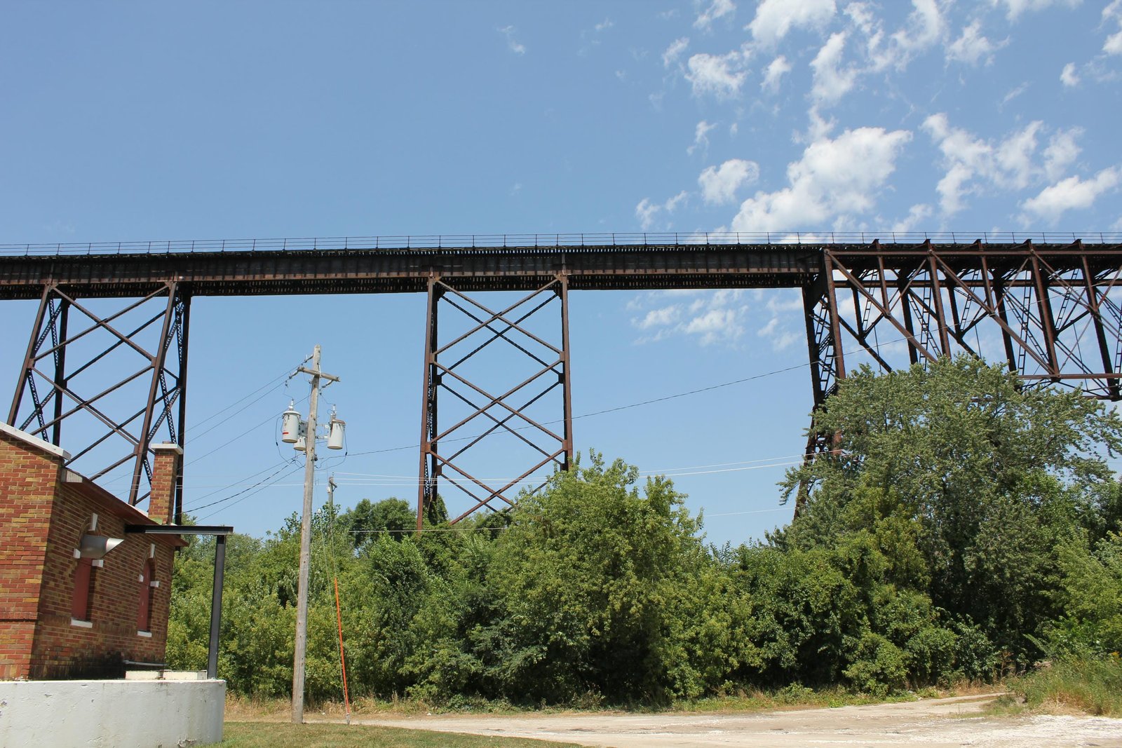
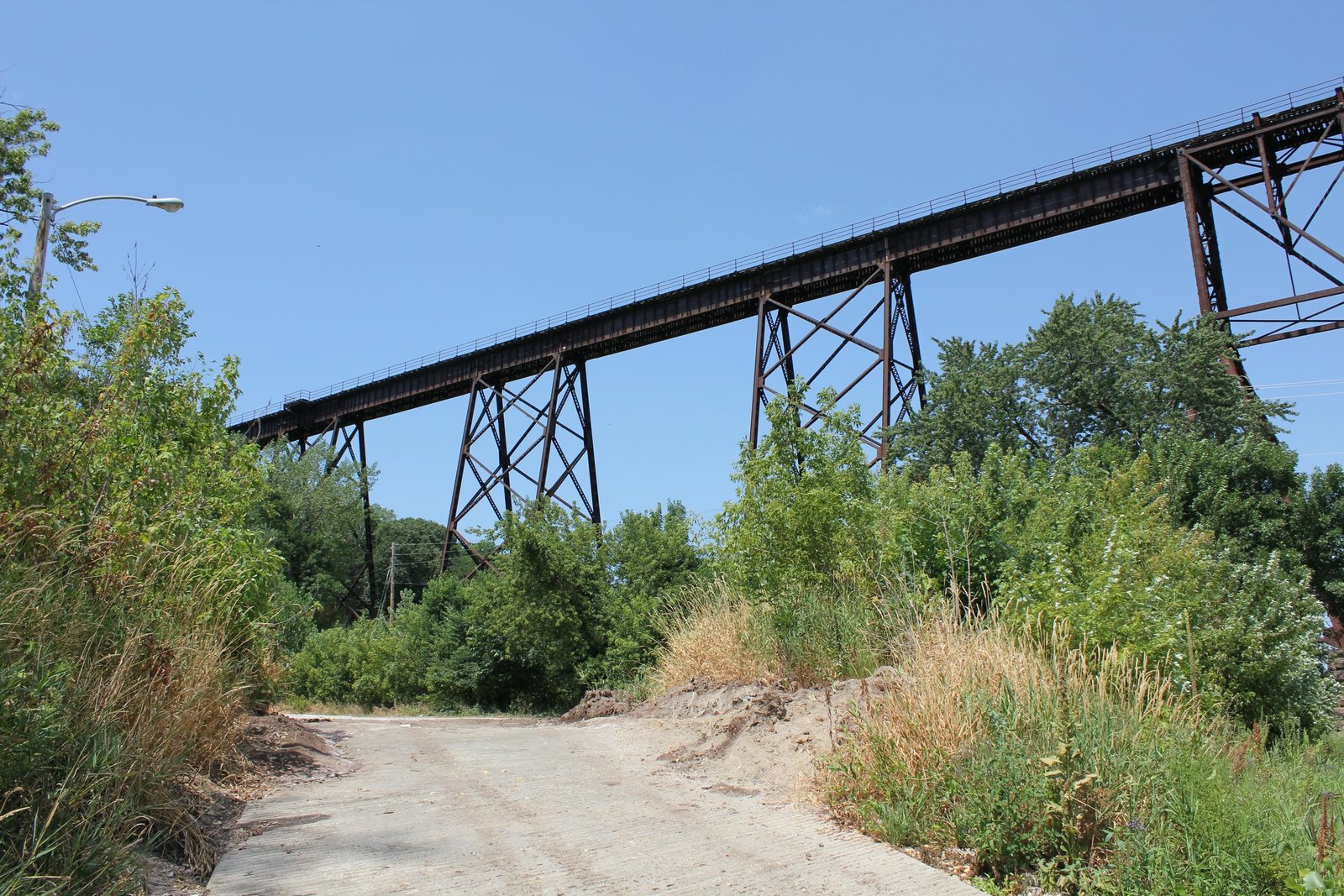
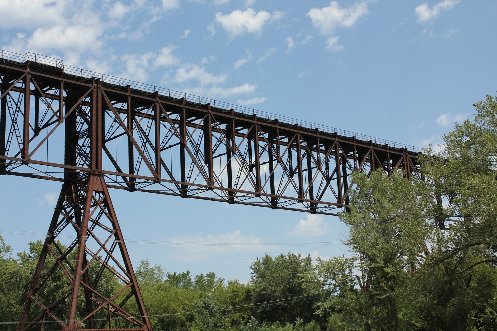
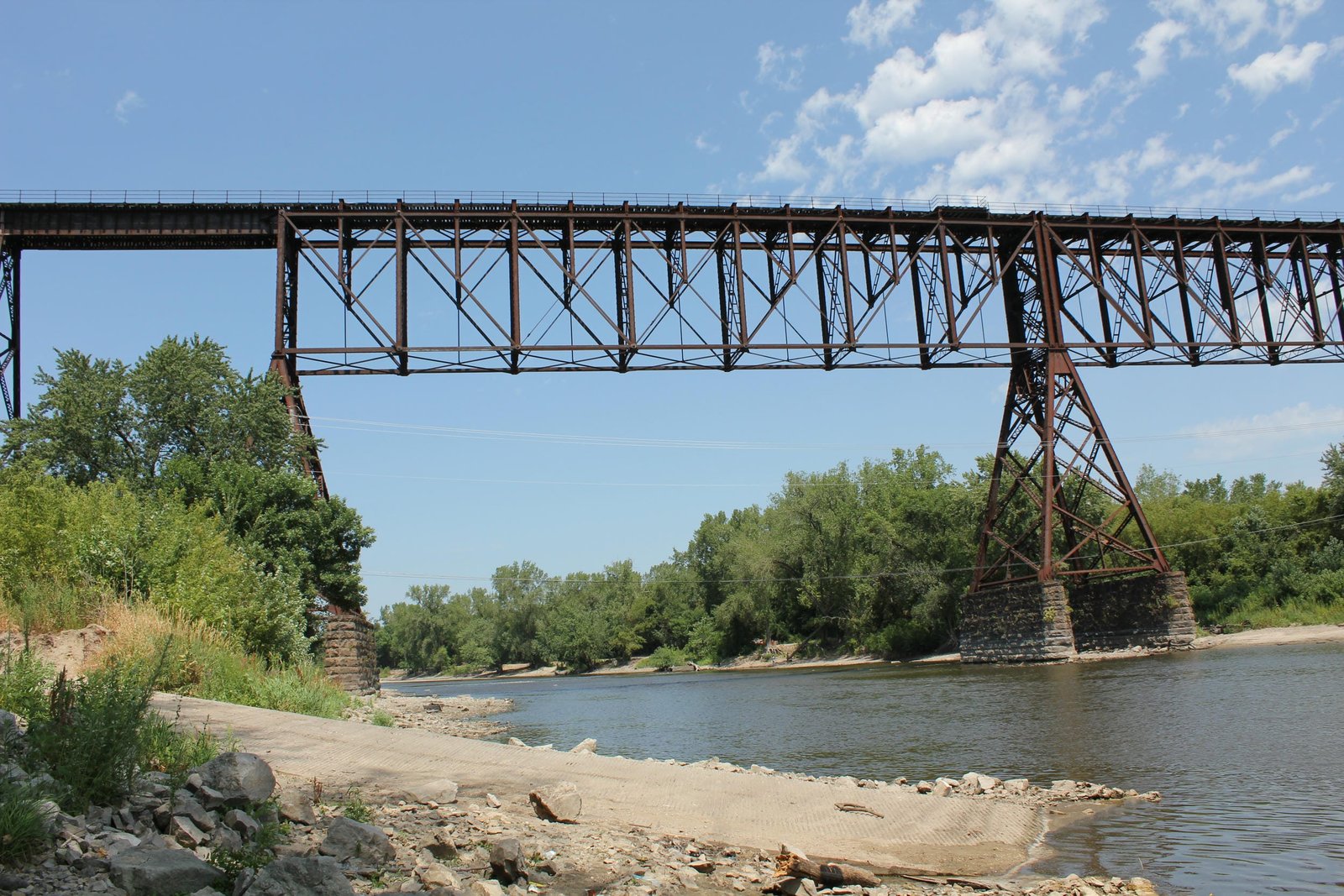
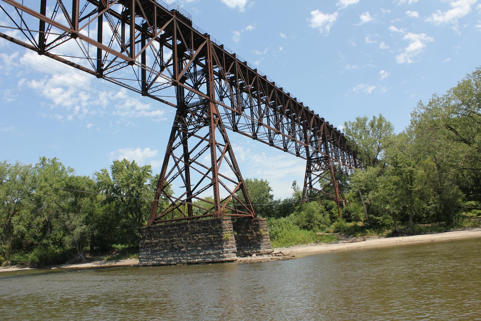
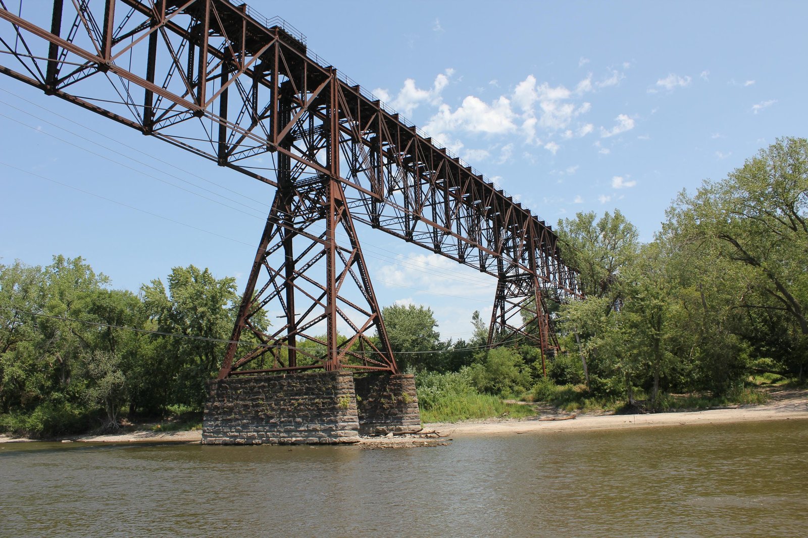
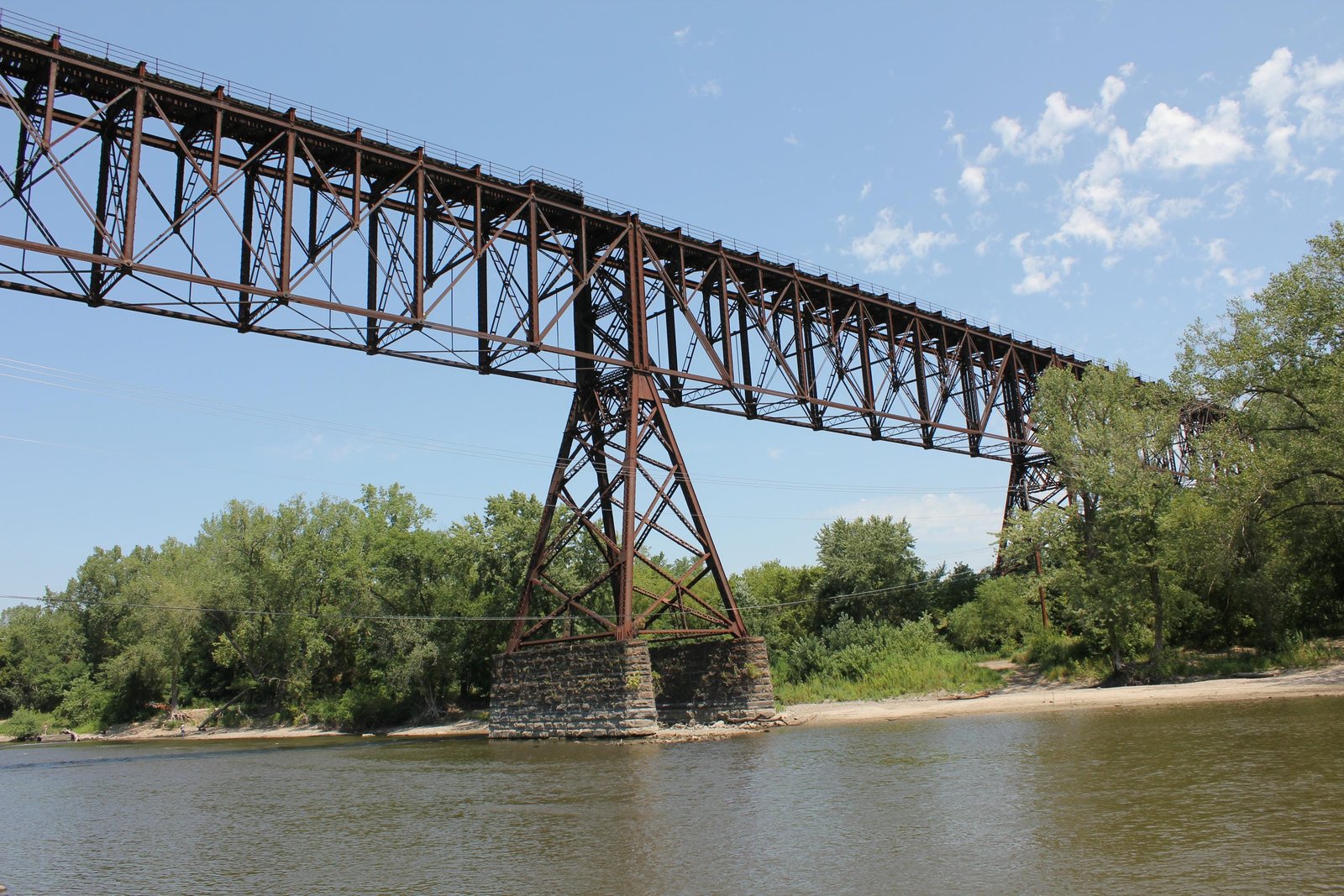
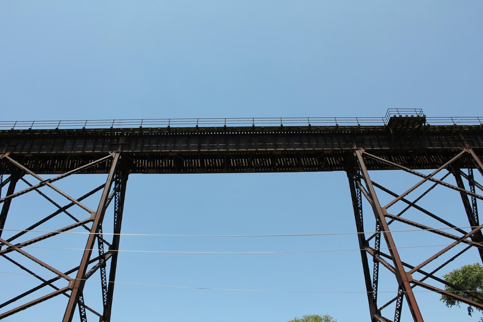
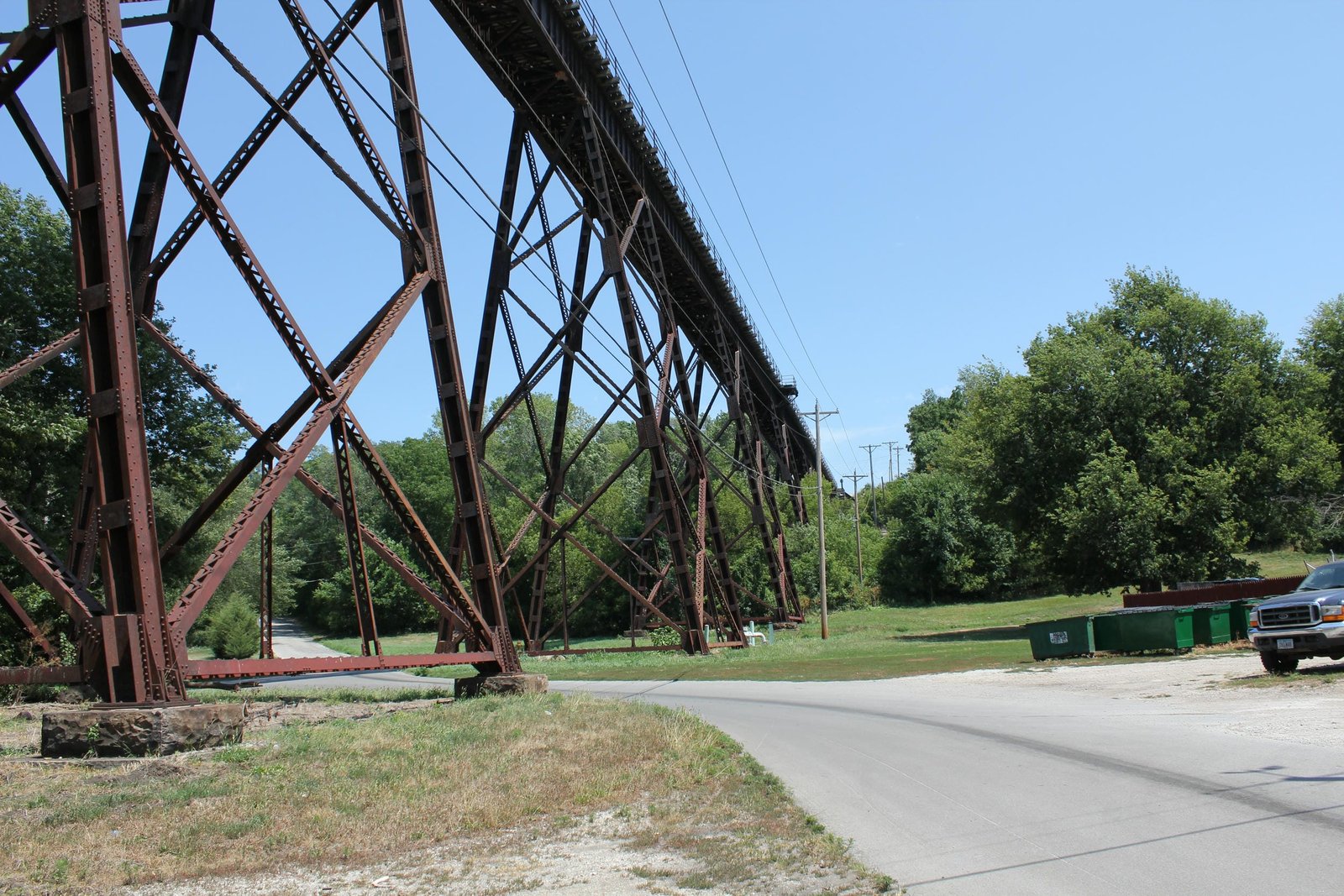
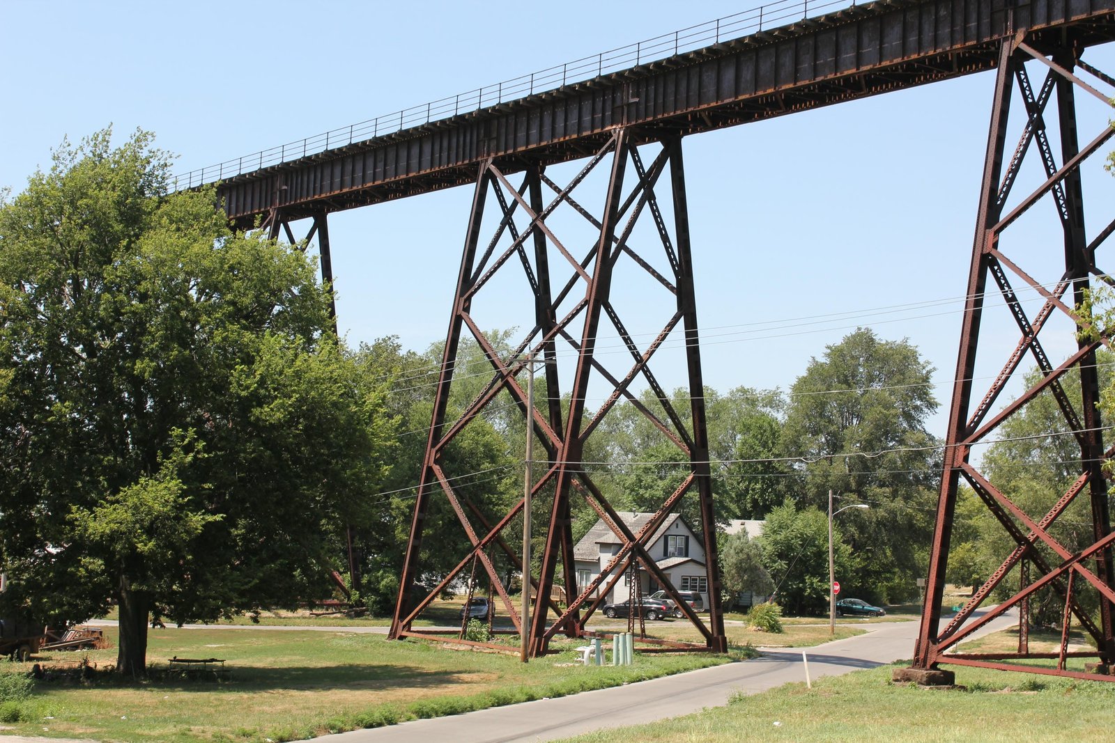
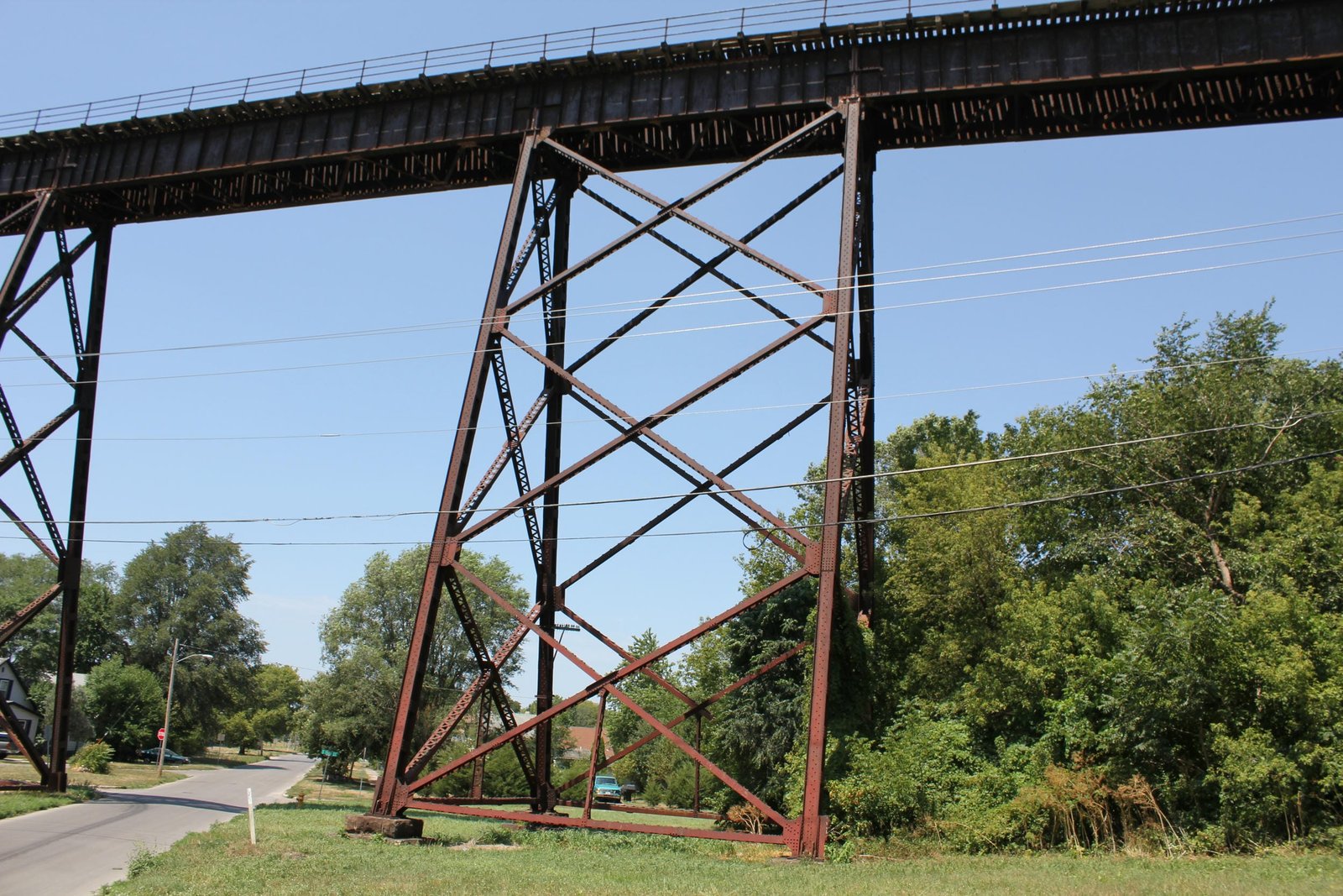
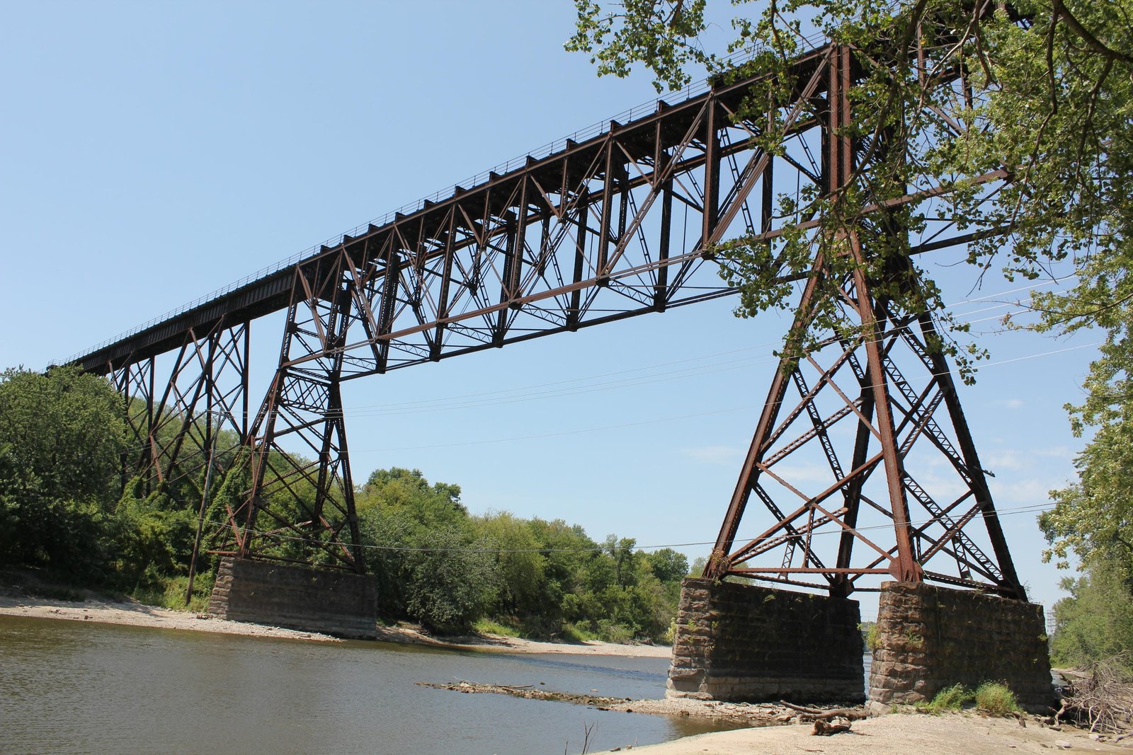
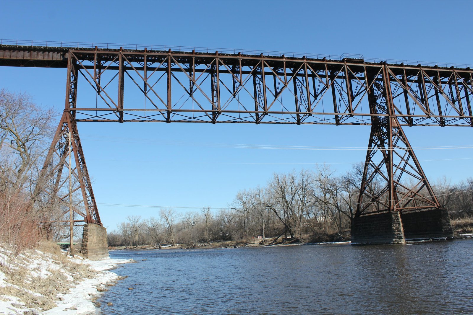
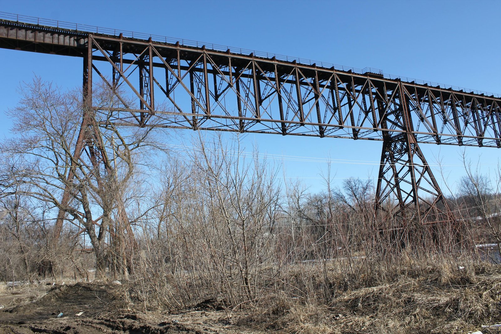
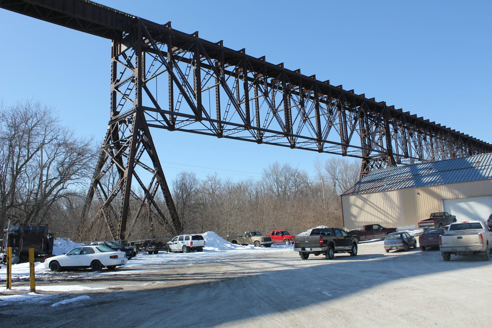
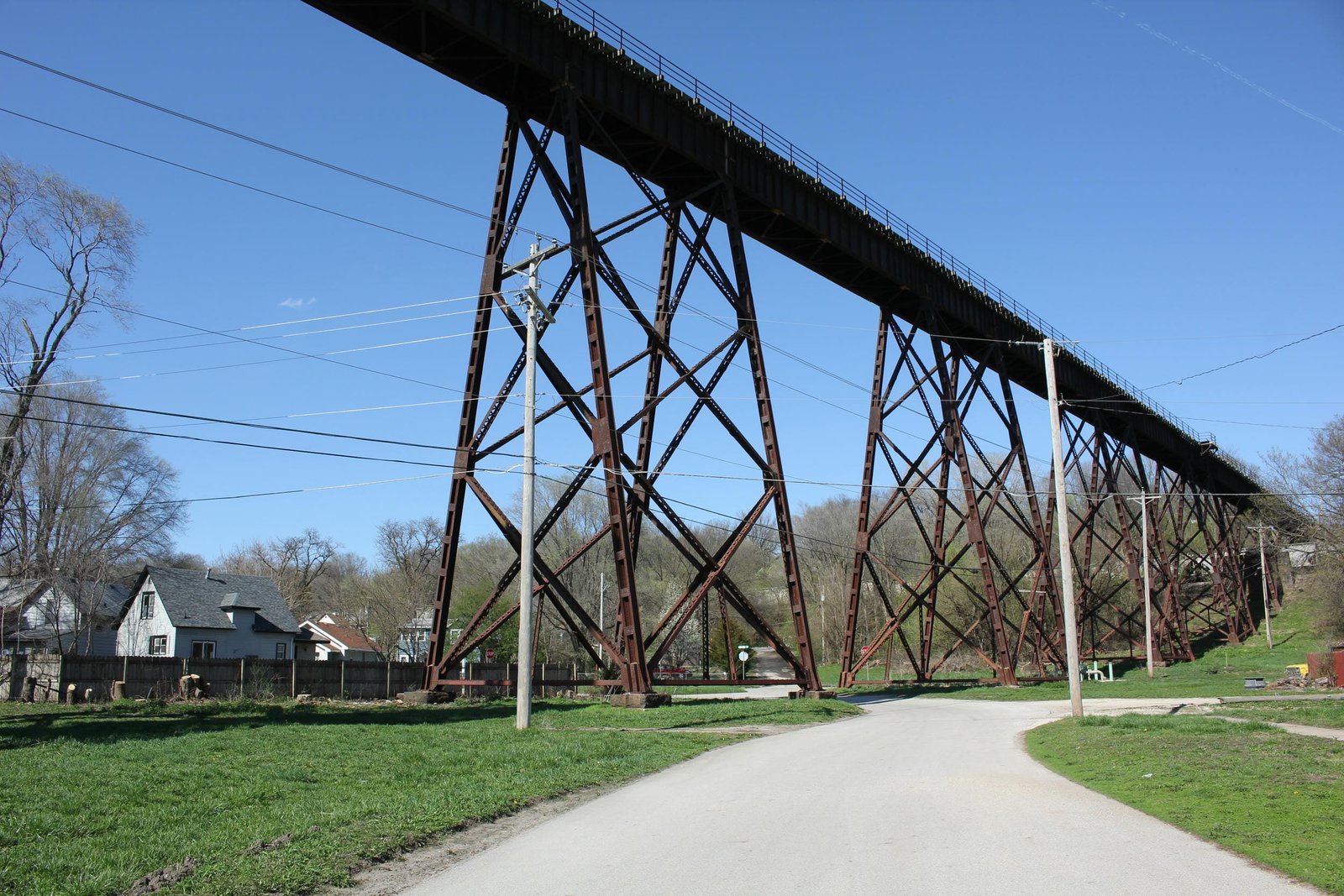
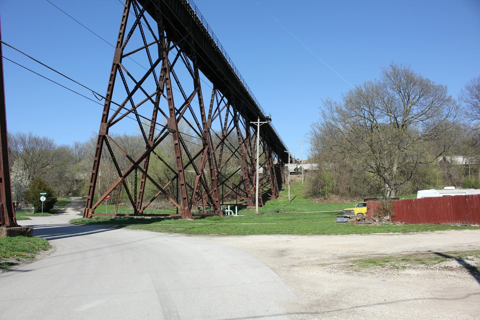
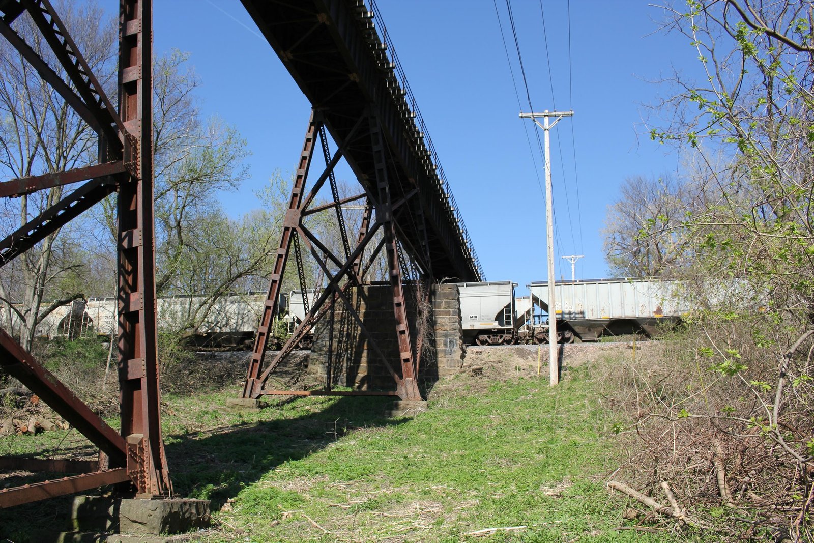
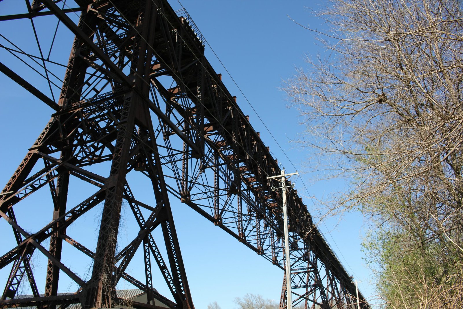
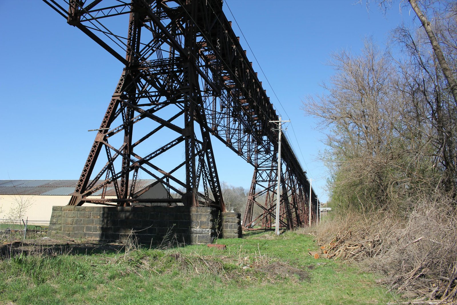
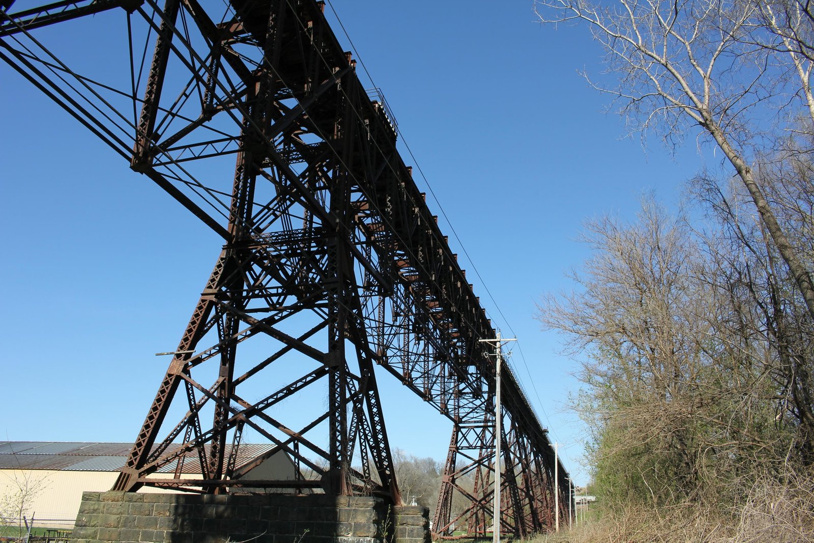
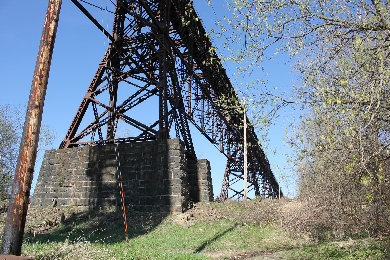
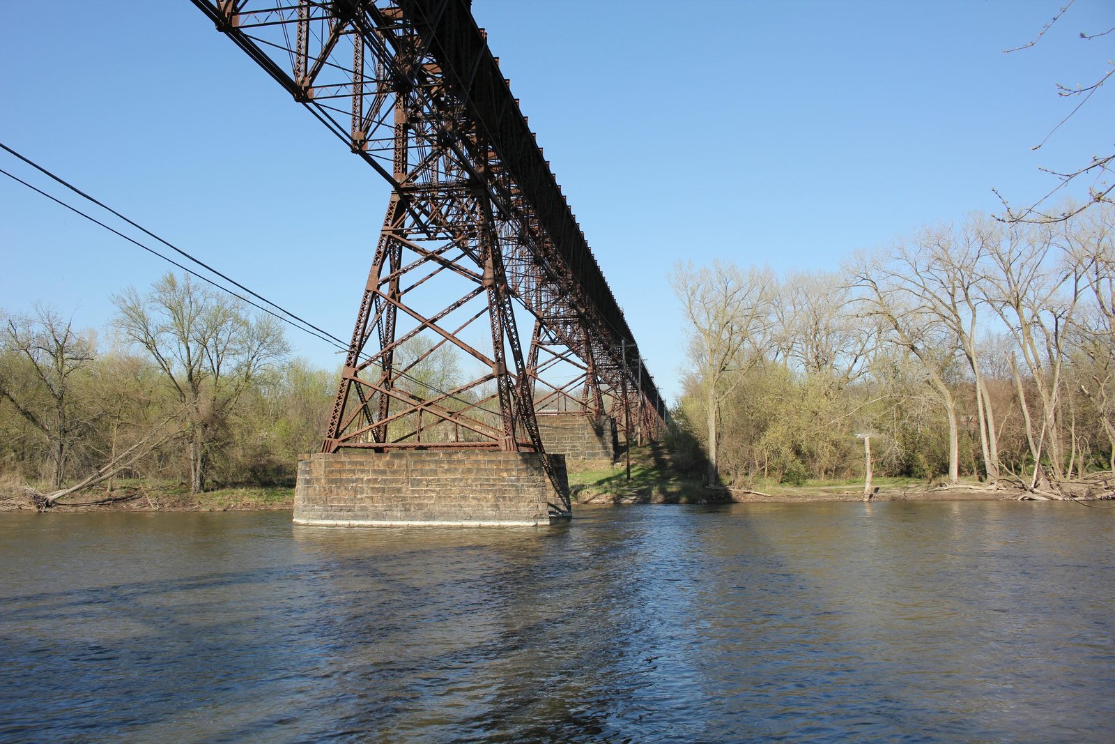
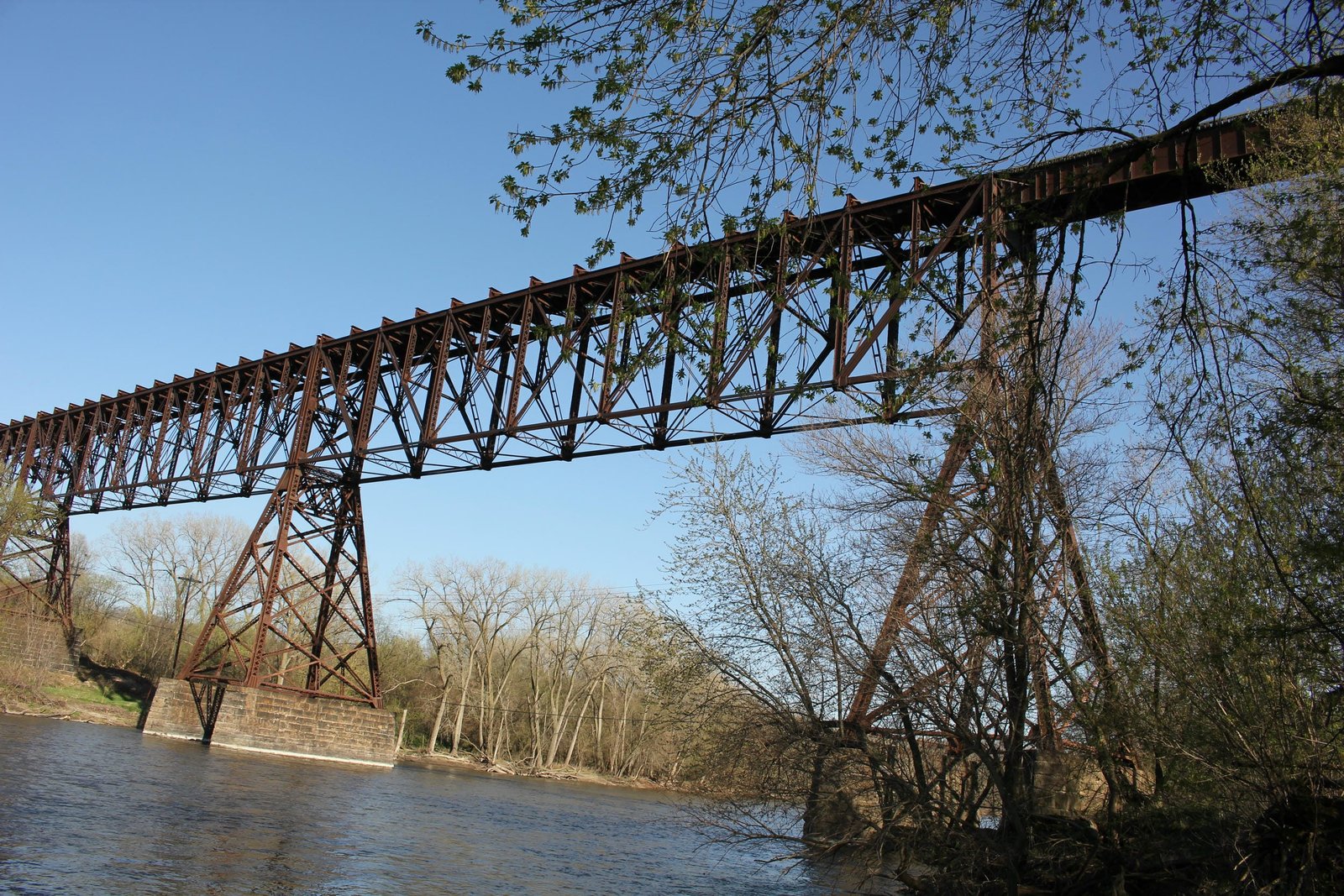
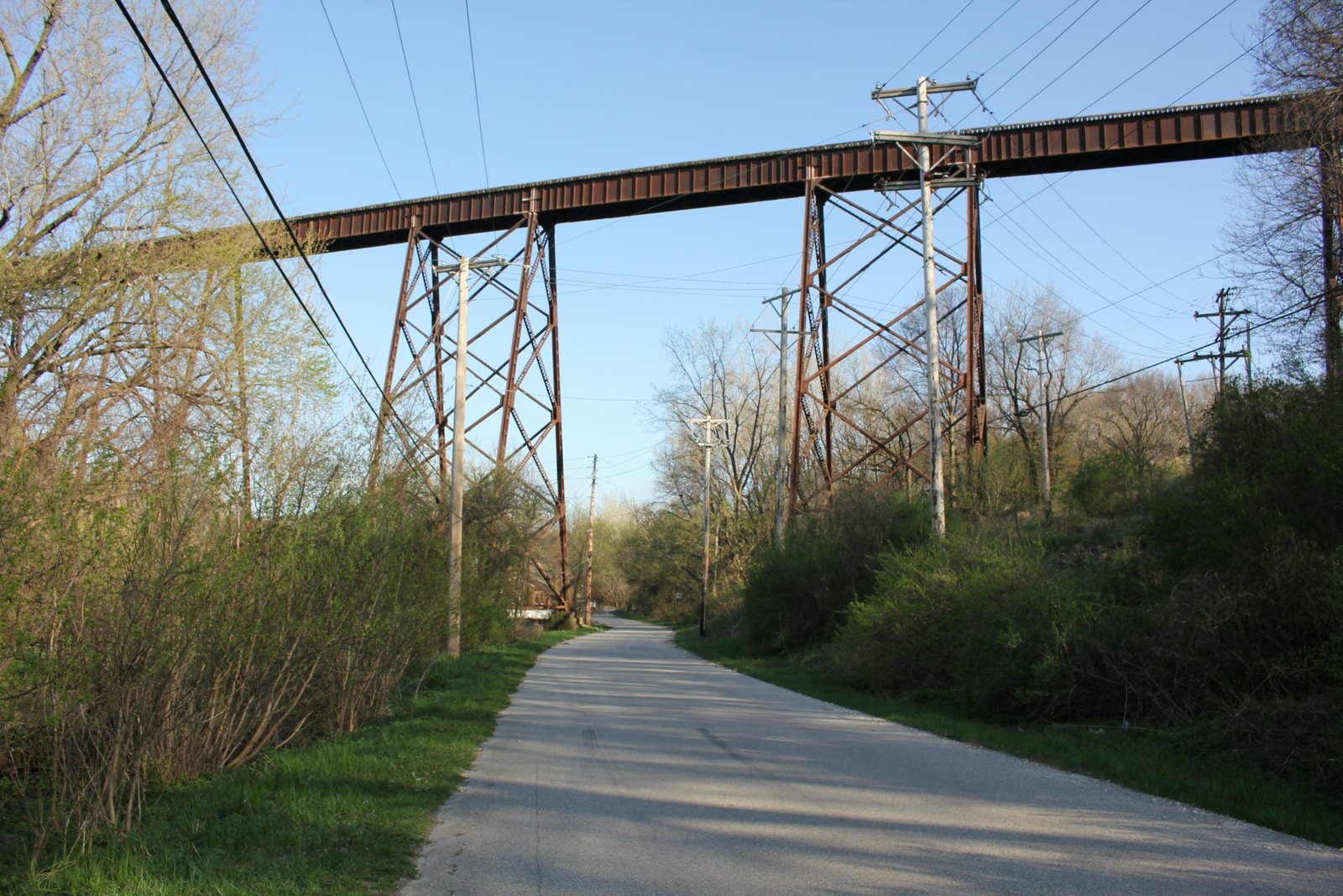
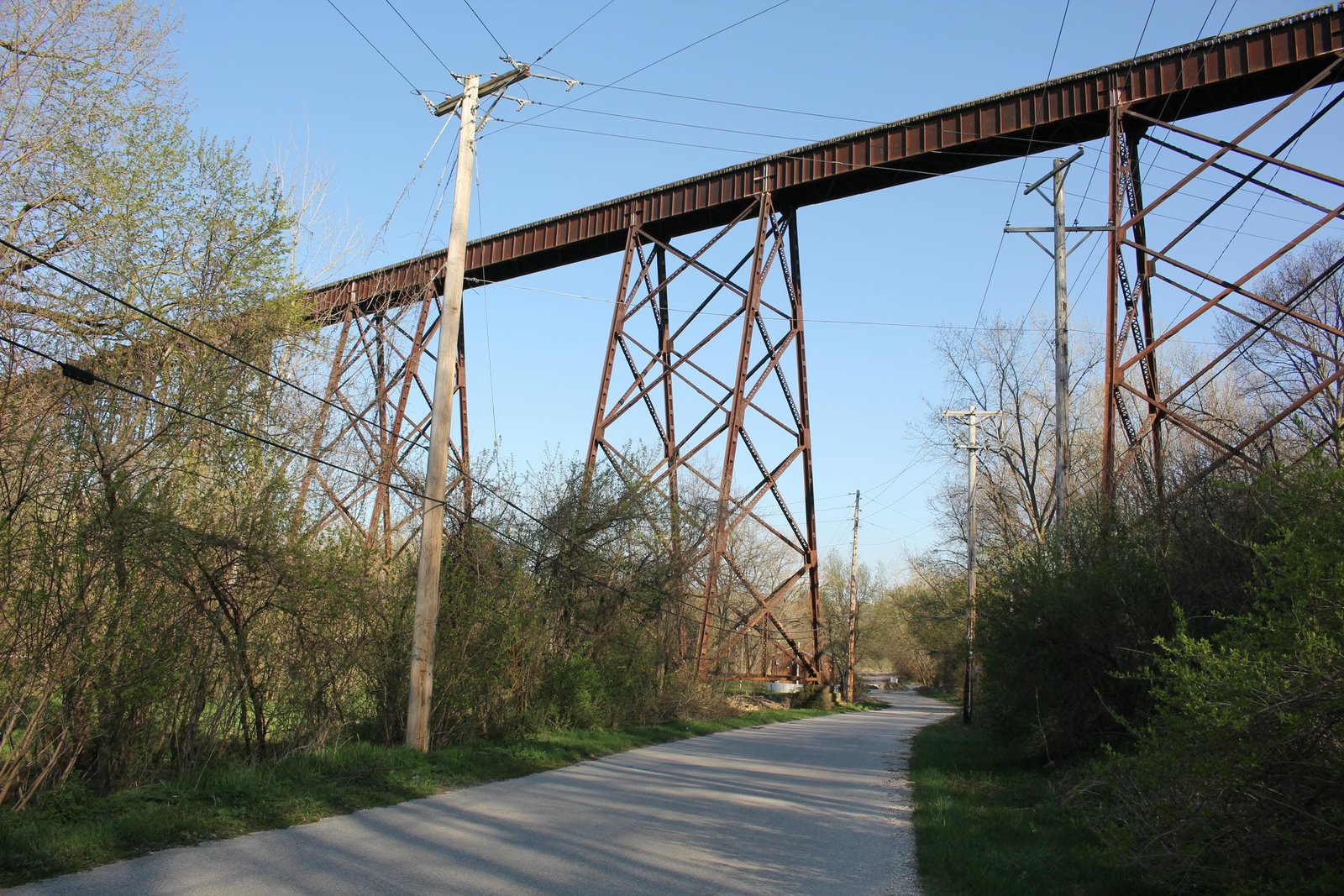
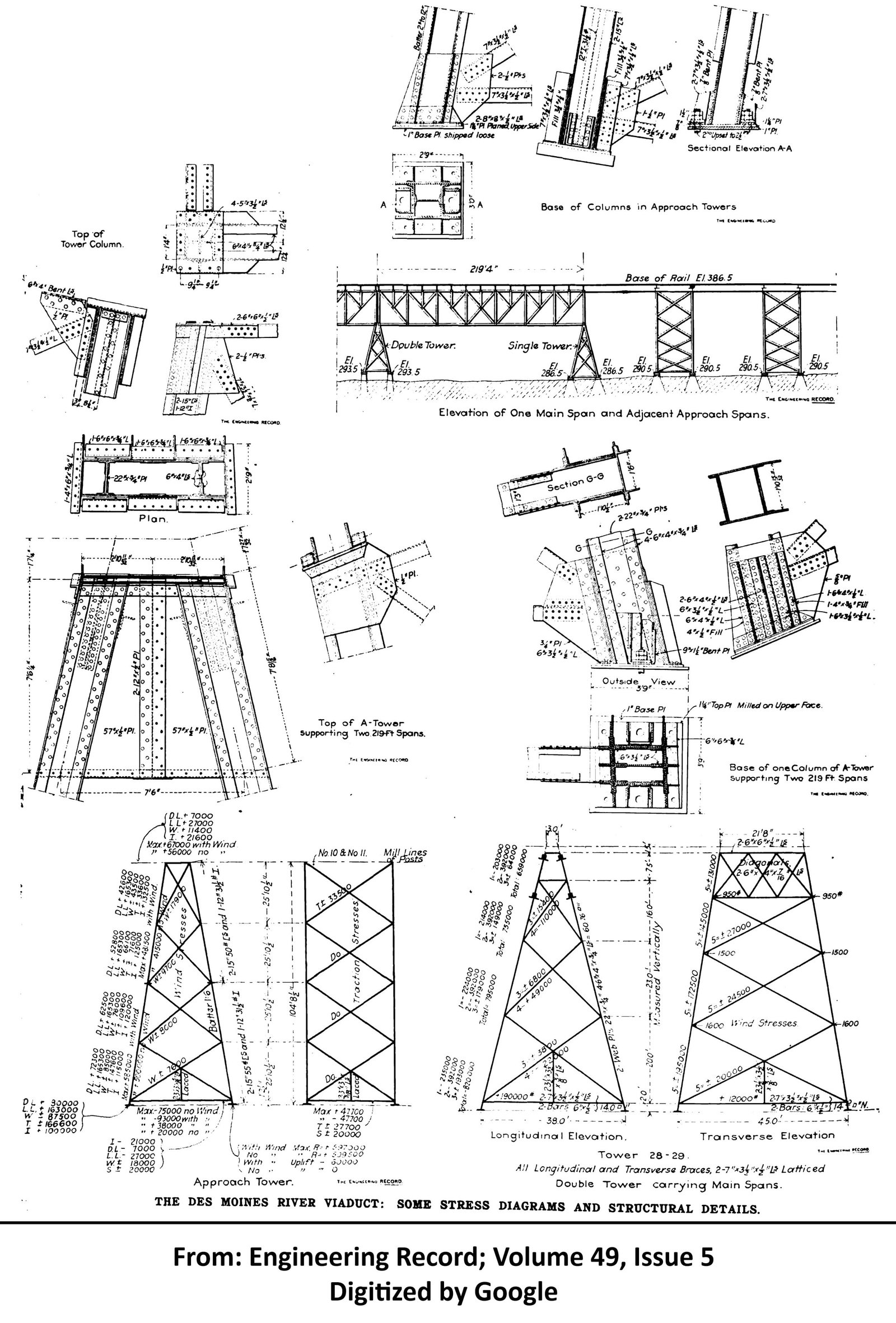
The viaduct consists of four 219-foot, 14-panel, pin-connected Baltimore deck truss spans, approached by long deck plate girder viaducts on either end. The truss spans are approached by nineteen deck plate girder spans on the east end and eleven deck plate girder spans on the west end. The east approach consists of nine 75-foot spans and ten 38-foot spans, of which nine are used as tower spans, with the easternmost span also consisting of a 38-foot span. The west approach consists of six 75-foot spans and five 38-foot tower spans. The truss spans are set onto A-frame towers on stone piers, while the remaining towers consist of a more typical design set onto stone pedestals and stone piers. The entire length of the bridge is 2,582 feet long and the bridge is approximately 138 feet tall at its highest point (Authors note: some sources indicate the bridge is 182 feet tall, but topographic data indicates 138 feet is more accurate). On the east approach, span #2 crosses a Canadian National Railway (former IC) yard; span #9 crosses 11th Avenue; span #11 crosses 15th Street and span #17 crosses 12th Avenue. Truss span #2 (span #21) crosses the former M&StL yard, which was abandoned in 1977. On the west end, span #28 crosses Avenue B.
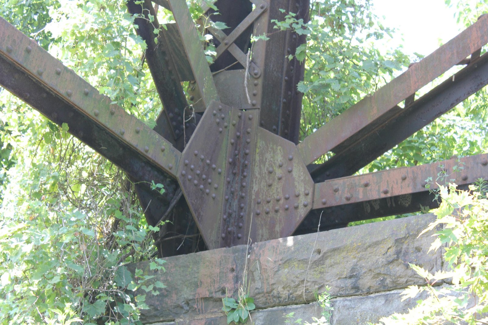
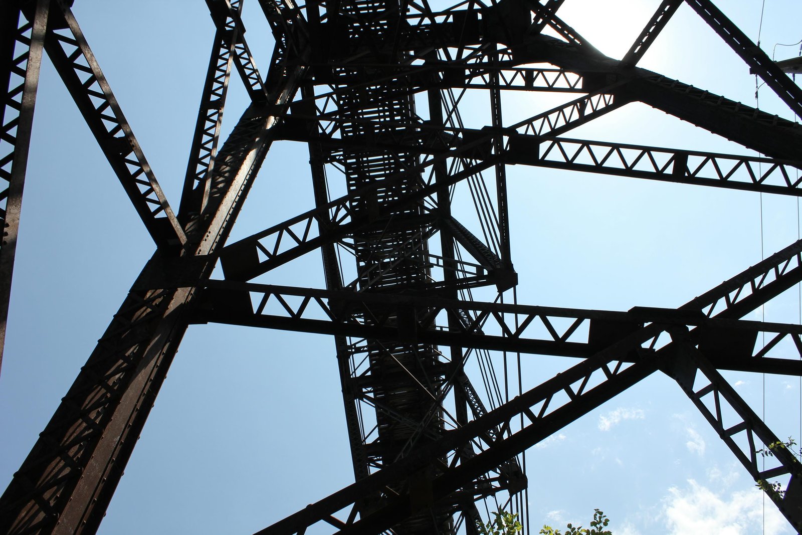
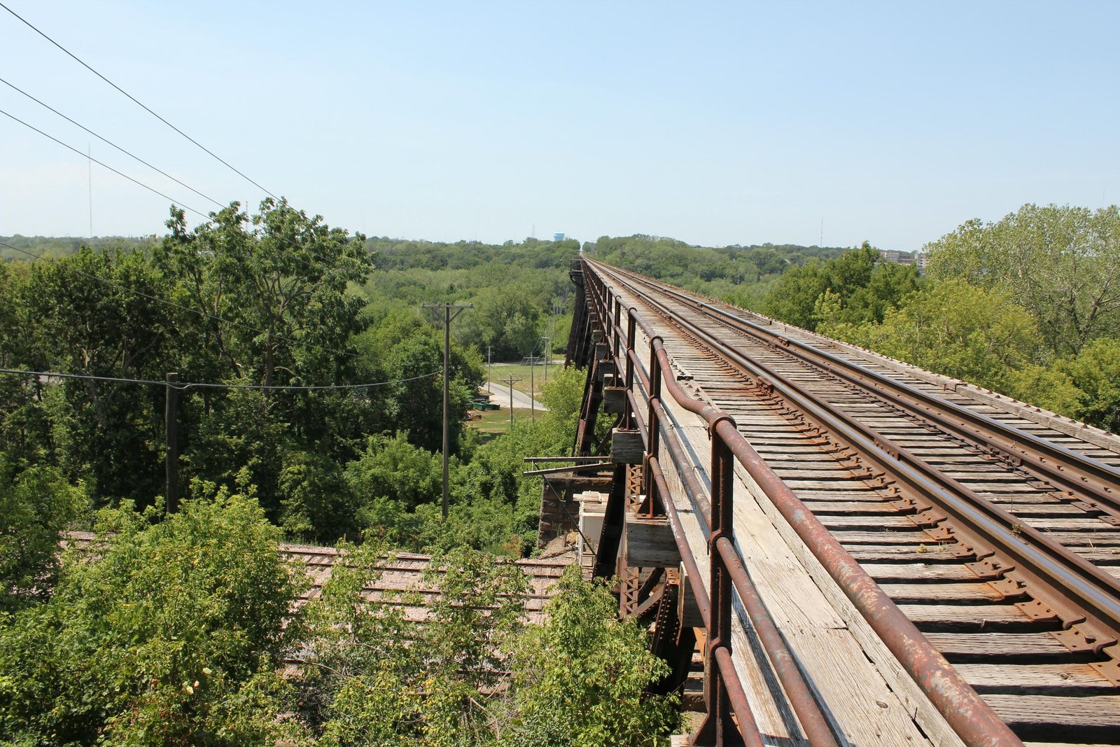
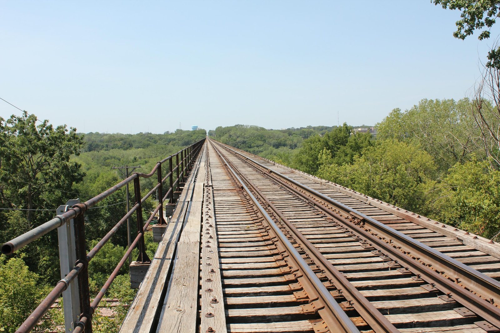
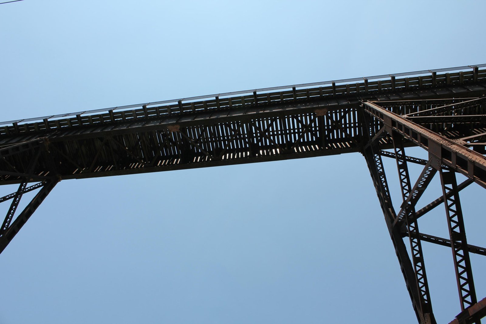
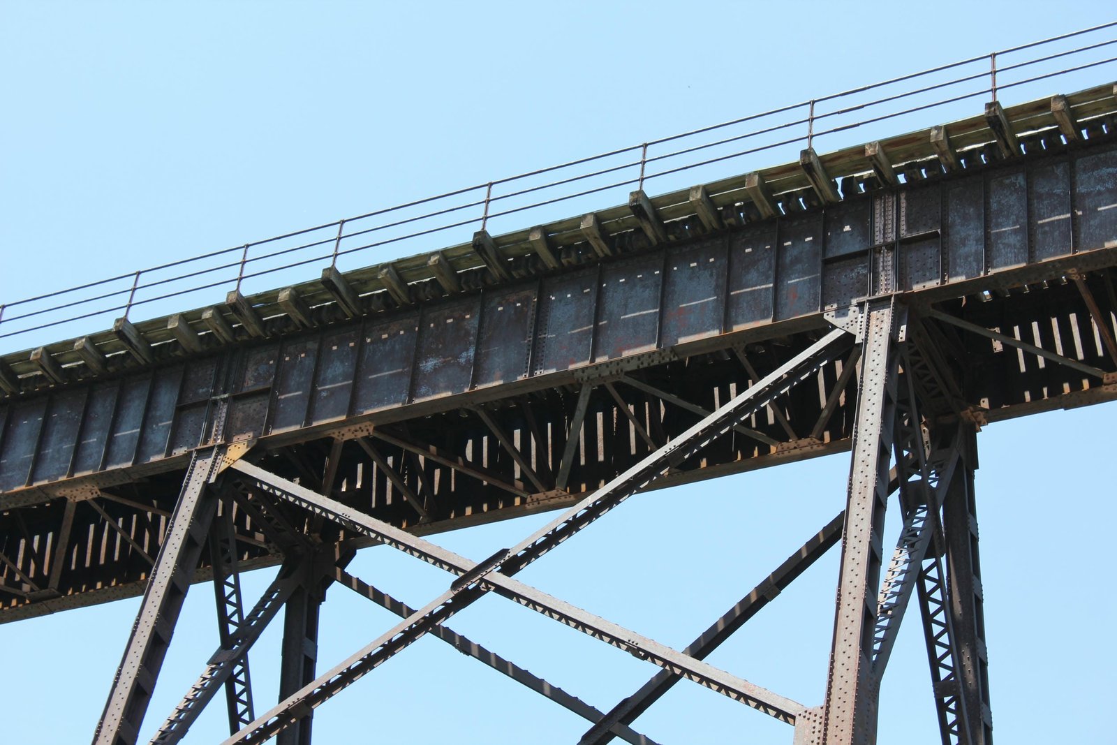
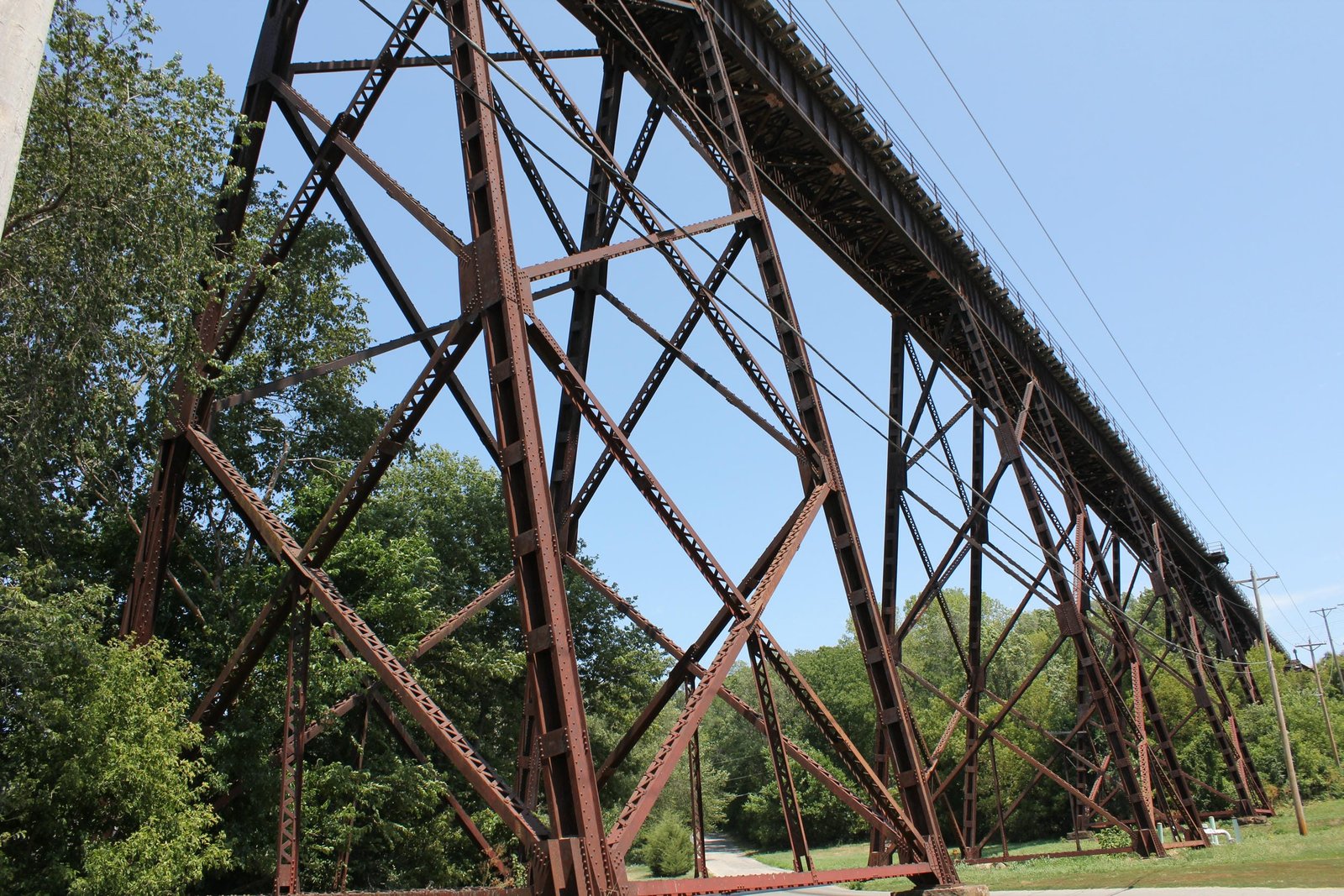
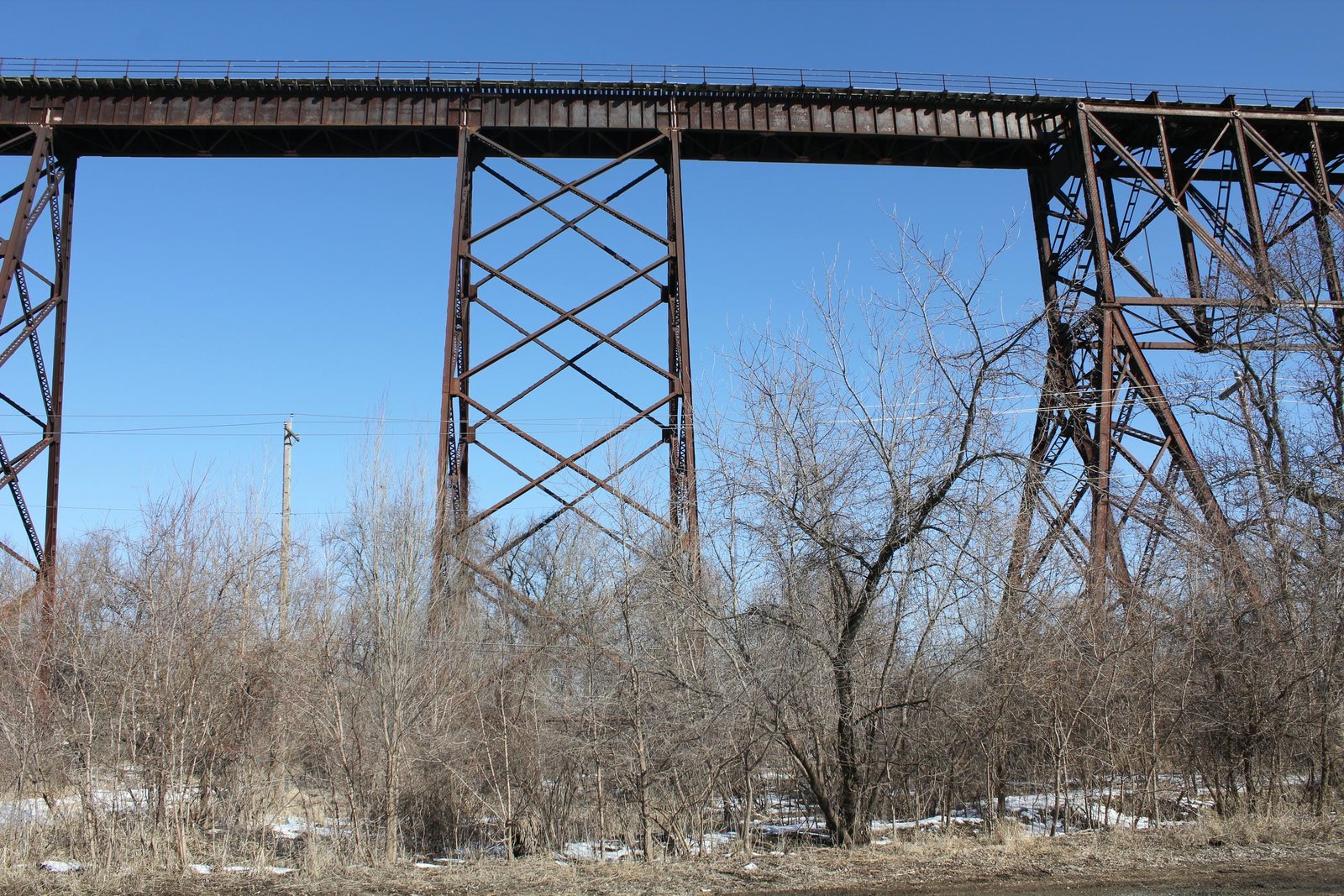
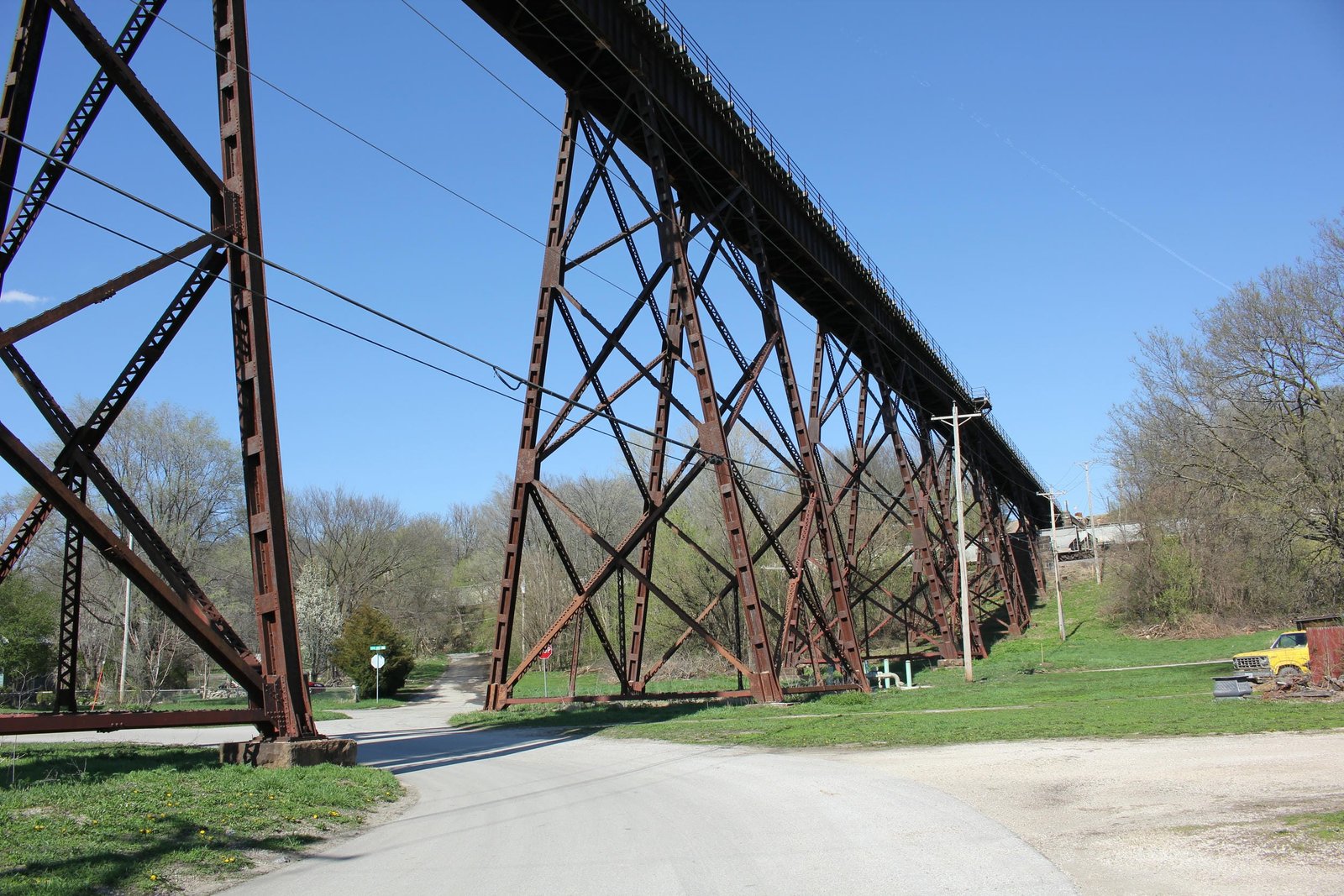
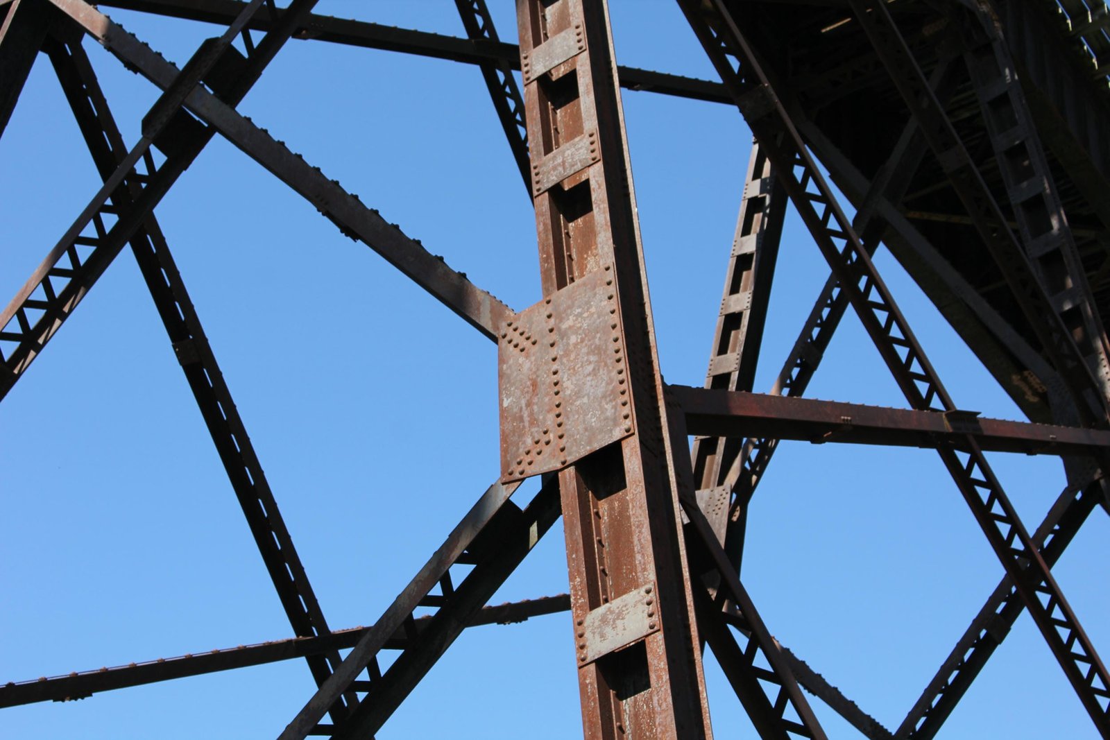
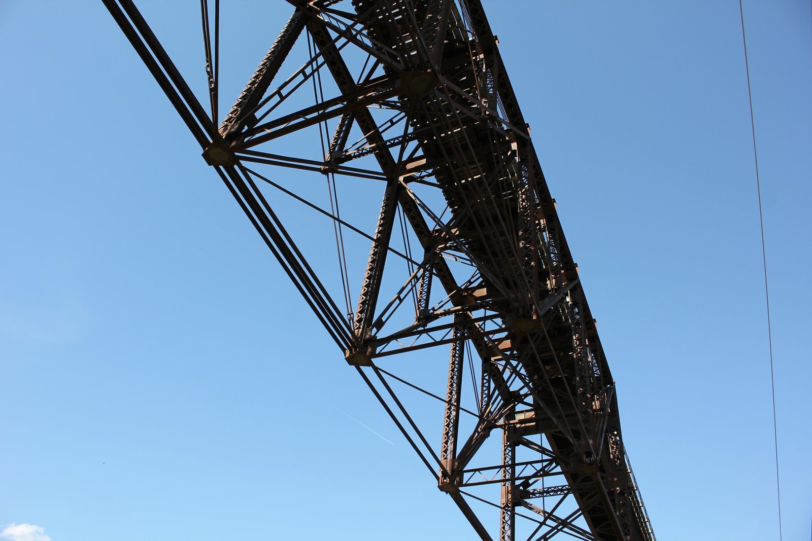
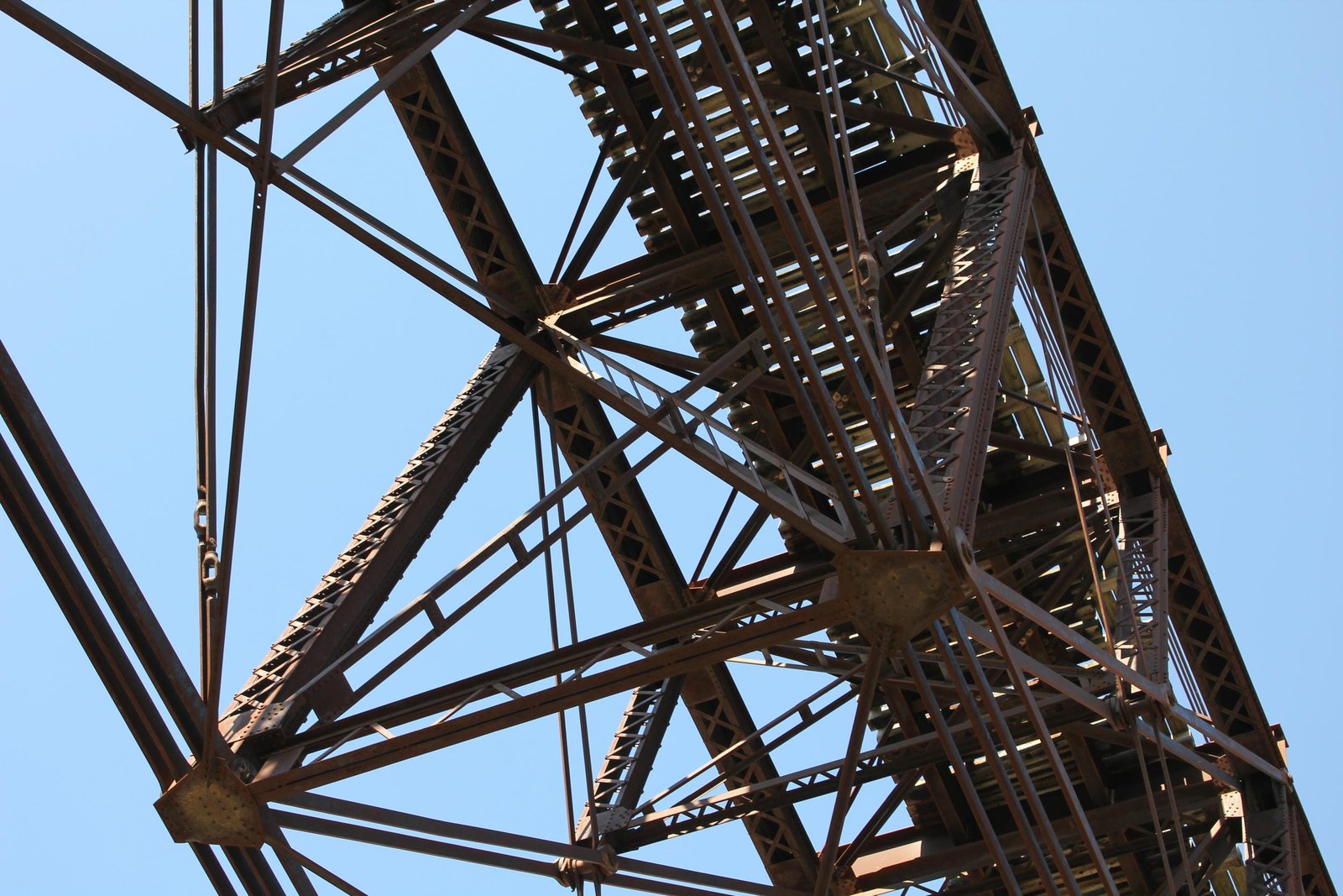
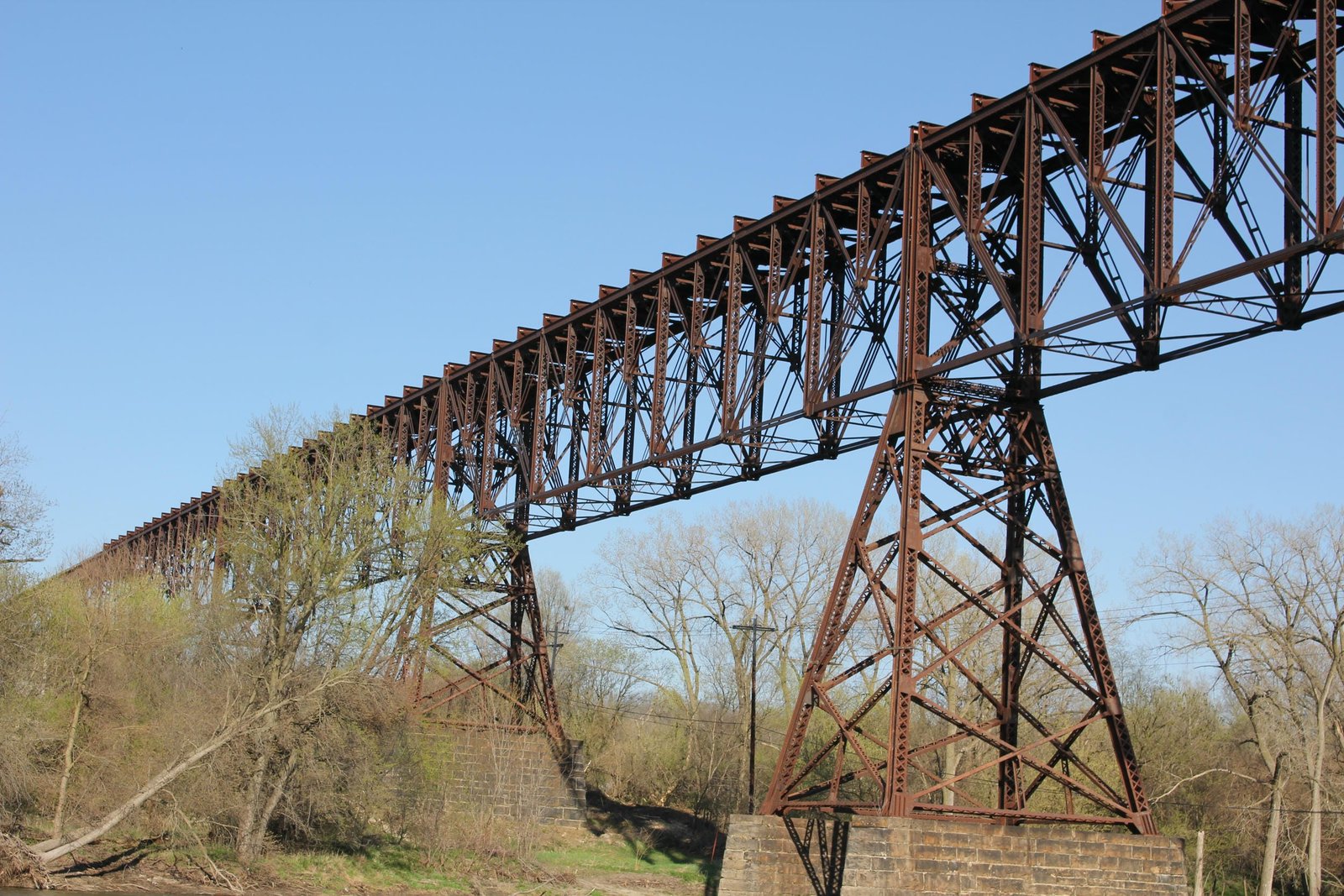
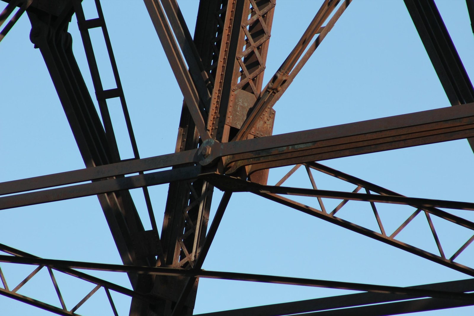
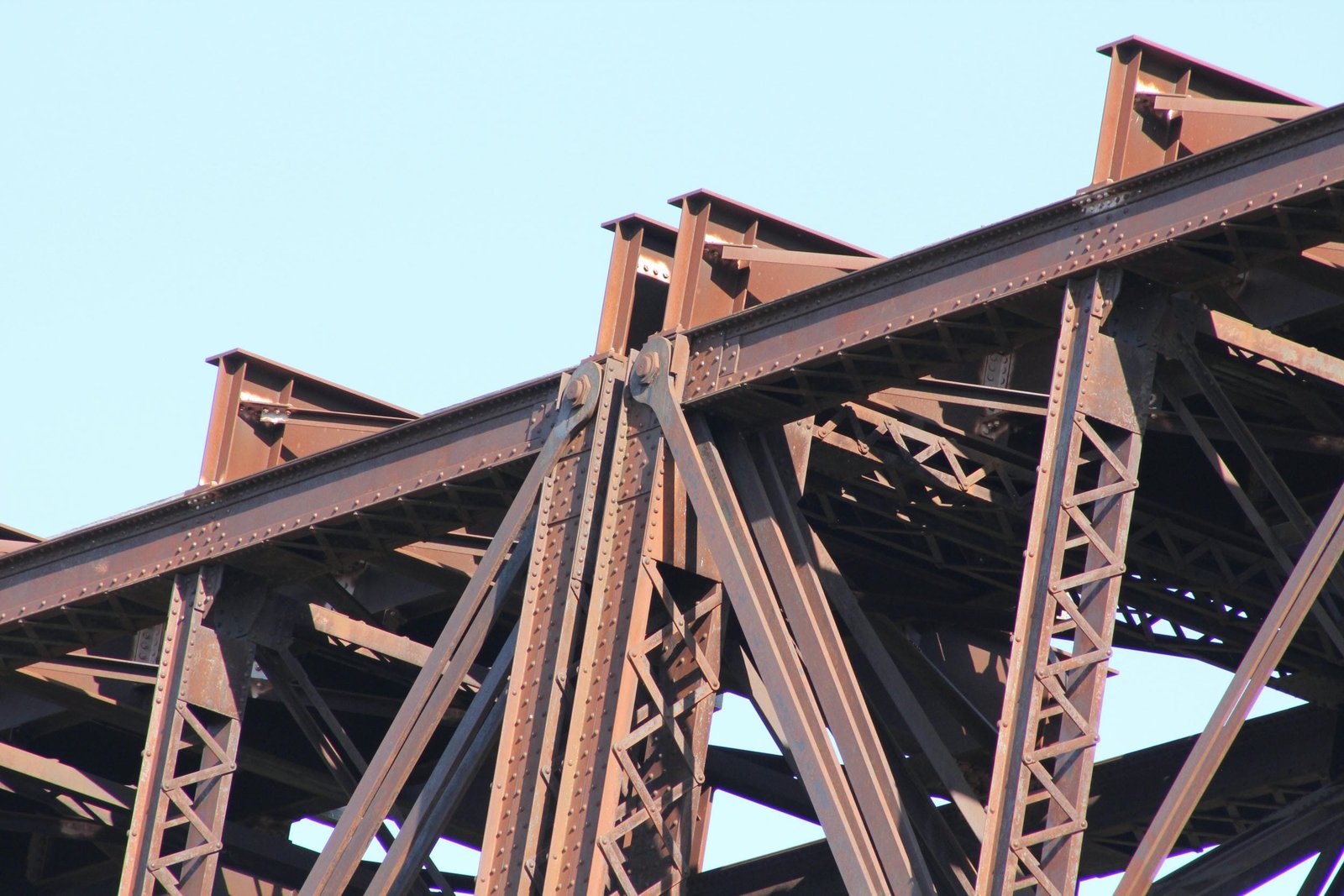
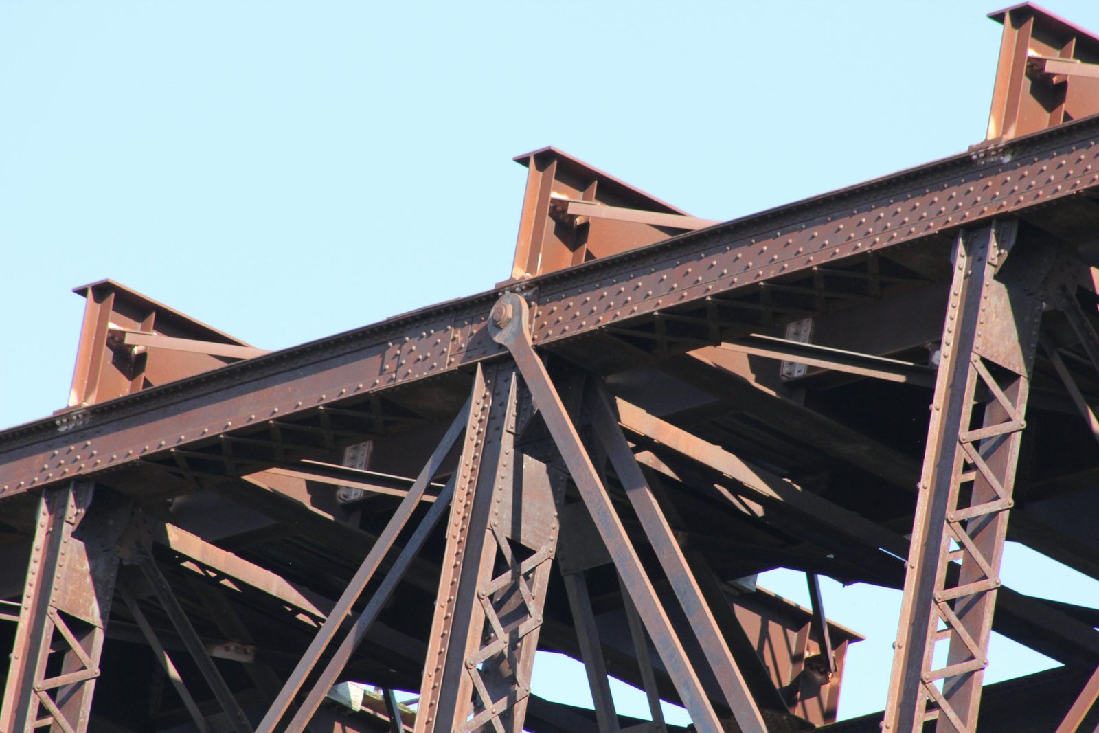
The truss spans are heavily constructed, using a combination of built-up members and eyebars, and the deck plate girder spans traditionally composed. The trusses are spaced 22-foot centers, and are 38 feet deep. Due to the Baltimore design, the trusses use seven standard panels, which are subdivided to create 14 total panels. All connections on the bottom chord are pin-connected, while only the standard panel points at the top chord are pin-connected. The sub-panel points are connected to the top chord by riveted connections. The top chords consist of a heavily built-up beams, with X-lacing on the bottom and a solid plate on the top. The bottom chord consists of eyebars, with a set of two at the second from last panels and a set of four at the middle panels. At the outermost panels, light built-up beams are used for the bottom chord. At the standard panels, full-depth vertical posts consist of heavily built-up beams, with X-lacing on both sides. At the sub-panels, half-depth vertical posts are considerably lighter, with V-lacing on both sides. The diagonal members are constructed of a combination of eyebars and rods, which are arranged so that heavier sets of eyebars are at the outer panels. The two truss webs are connected by a V-laced sway bar at the standard panel points and by a solid plate halfway up the truss at the sub-panel points. Lateral bracing between the trusses consists of two beams, constructed from L-shaped bars and connected by thin plates. These beams form an X-shape, and are used at both the panel points and sub-panel points. At the ends of the truss, two levels of these braces are used, along with heavy transverse V-laced beams at the top, middle and bottom of the truss. The original floor system consisted of two plate girder stringers and plate girder floorbeams, which were placed above the trusses. Both the upper and lower lateral bracing consists of standard angle plates. The trusses are connected to the A-towers by a pin at the top of the tower. The deck plate girder spans use a standard design, which has been modified to adapt to the use of towers. The 75-foot spans supported by towers were designed so that they could freely expand and contract with temperature changes, while the 38-foot spans are fixed to the towers and cannot expand or contract.
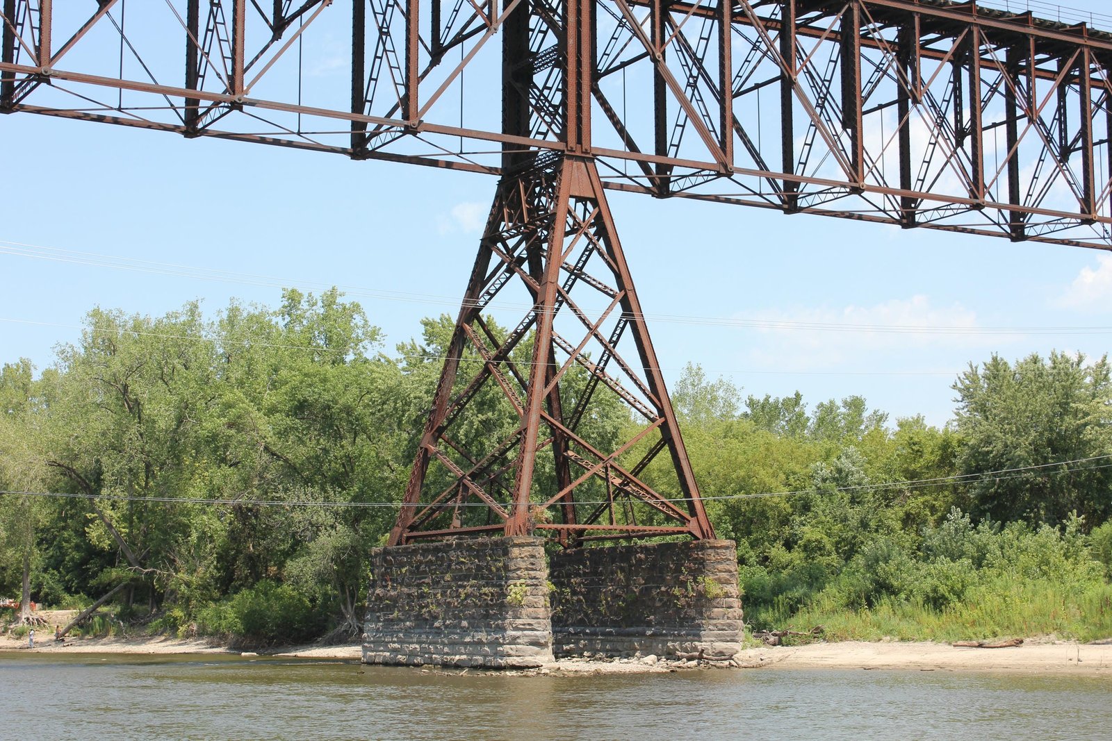
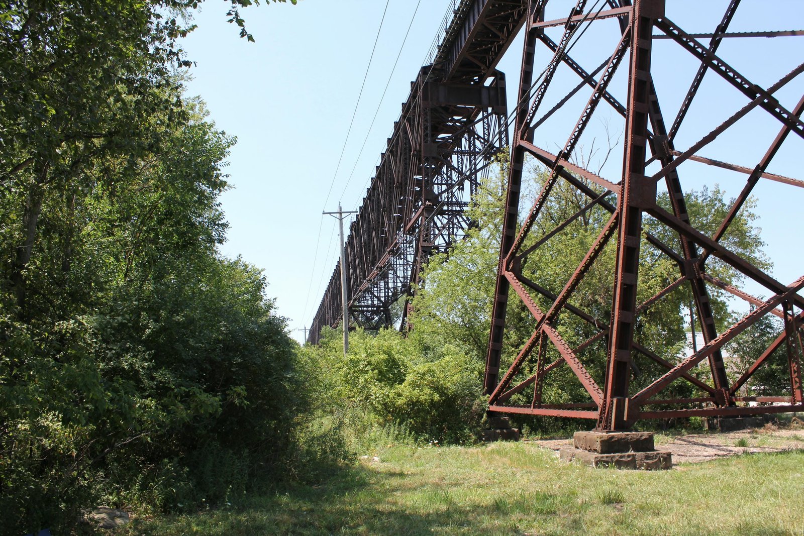
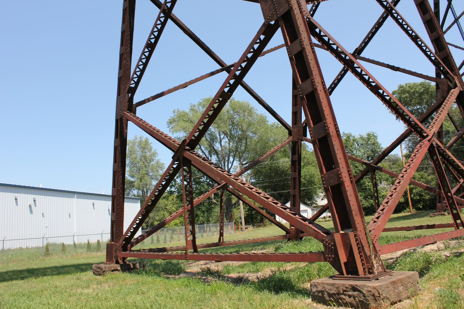
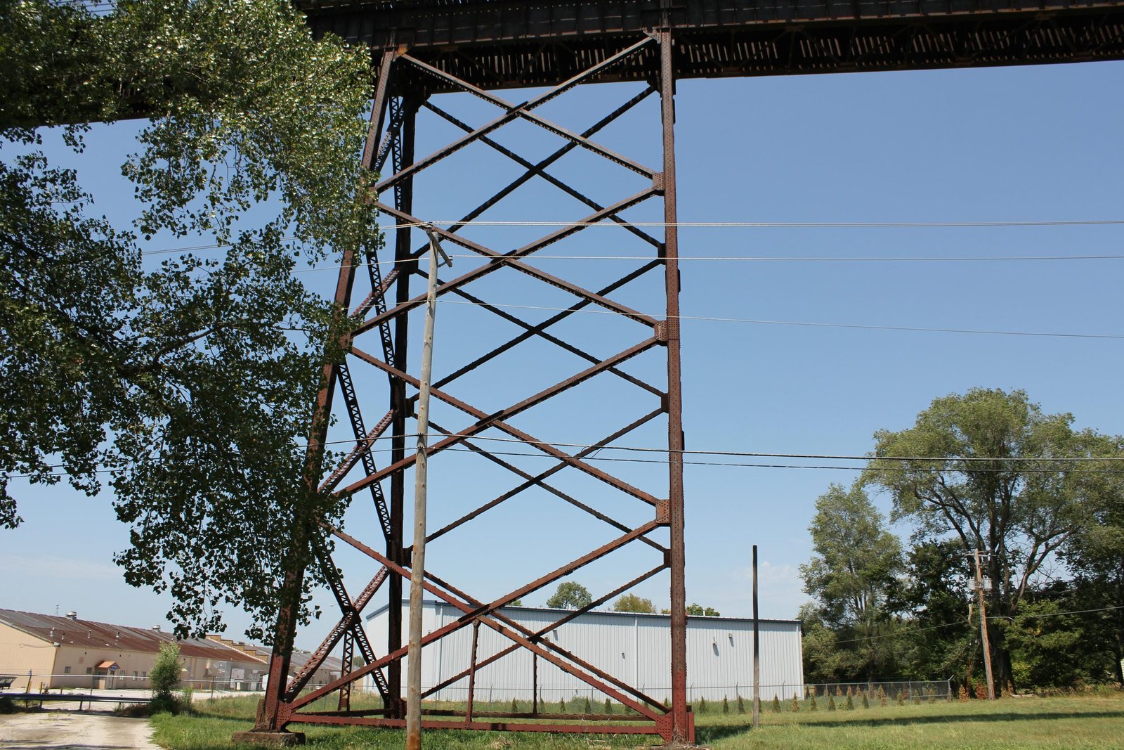
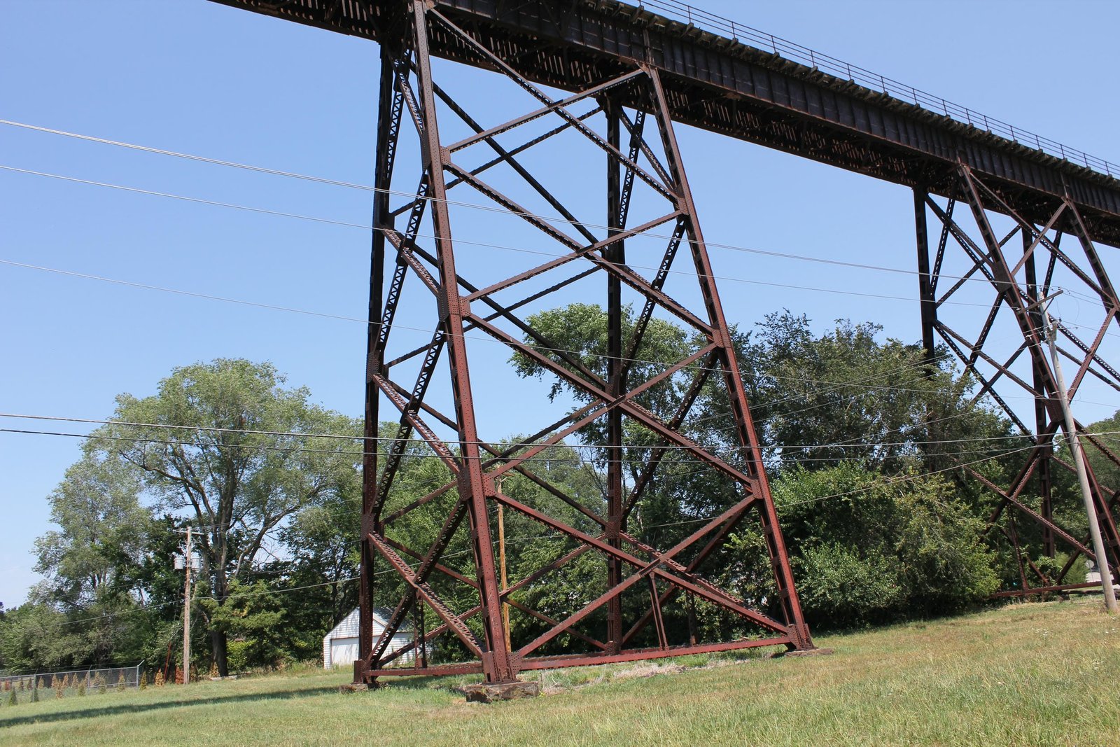
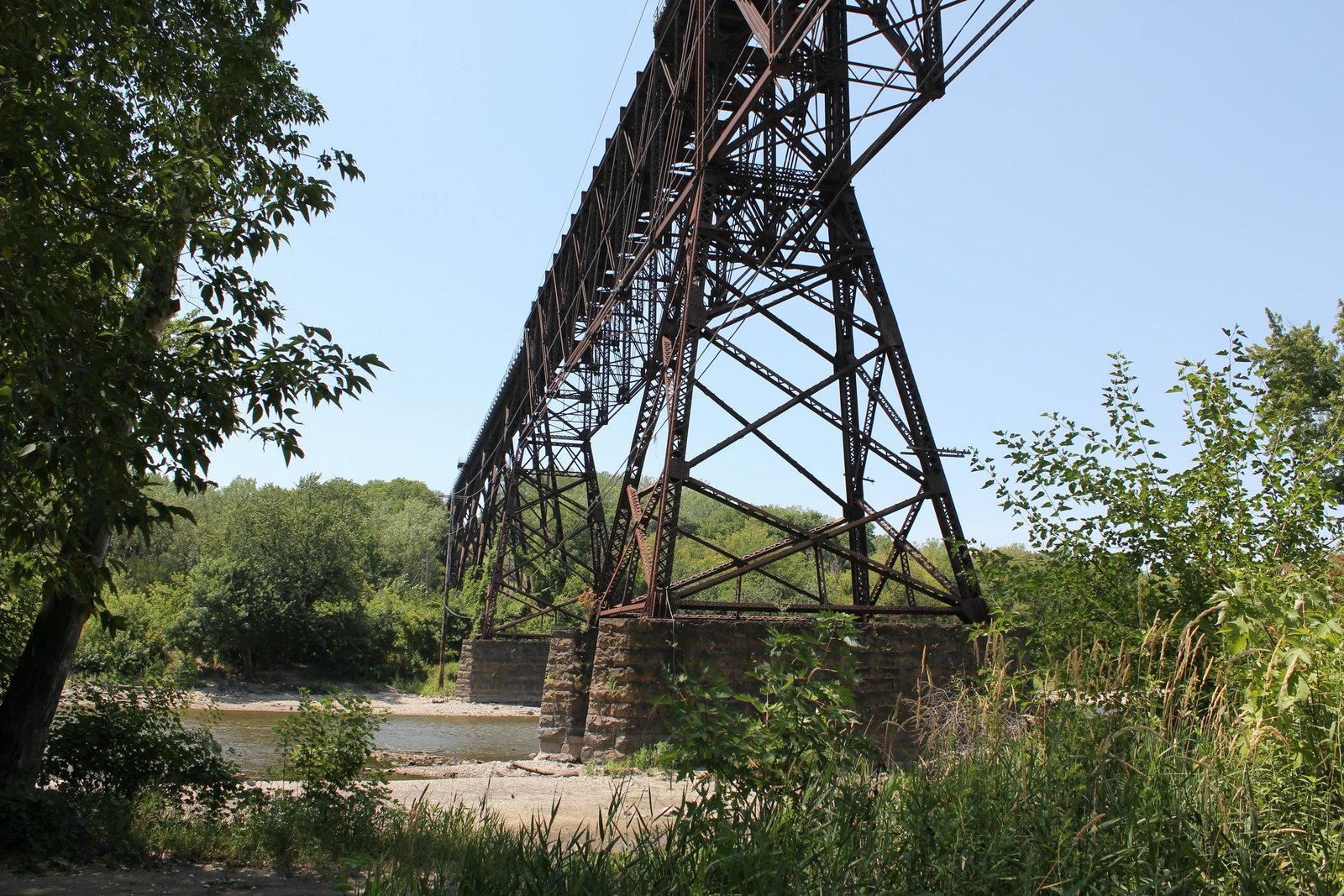
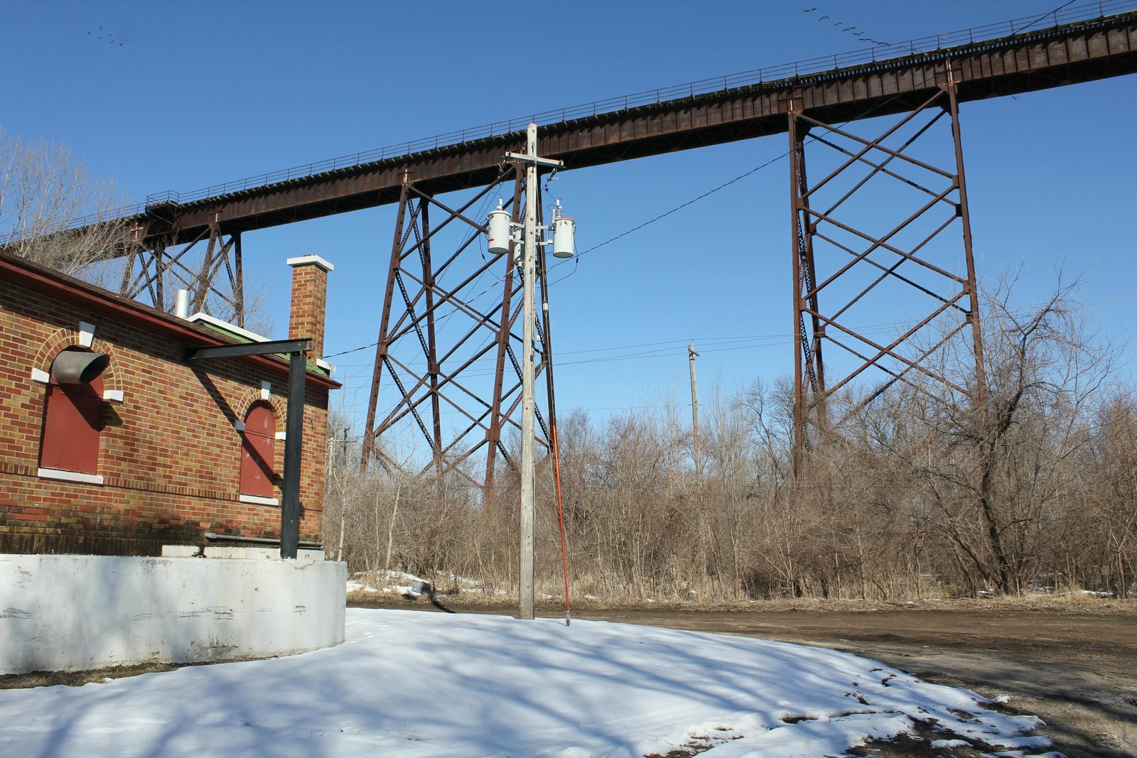
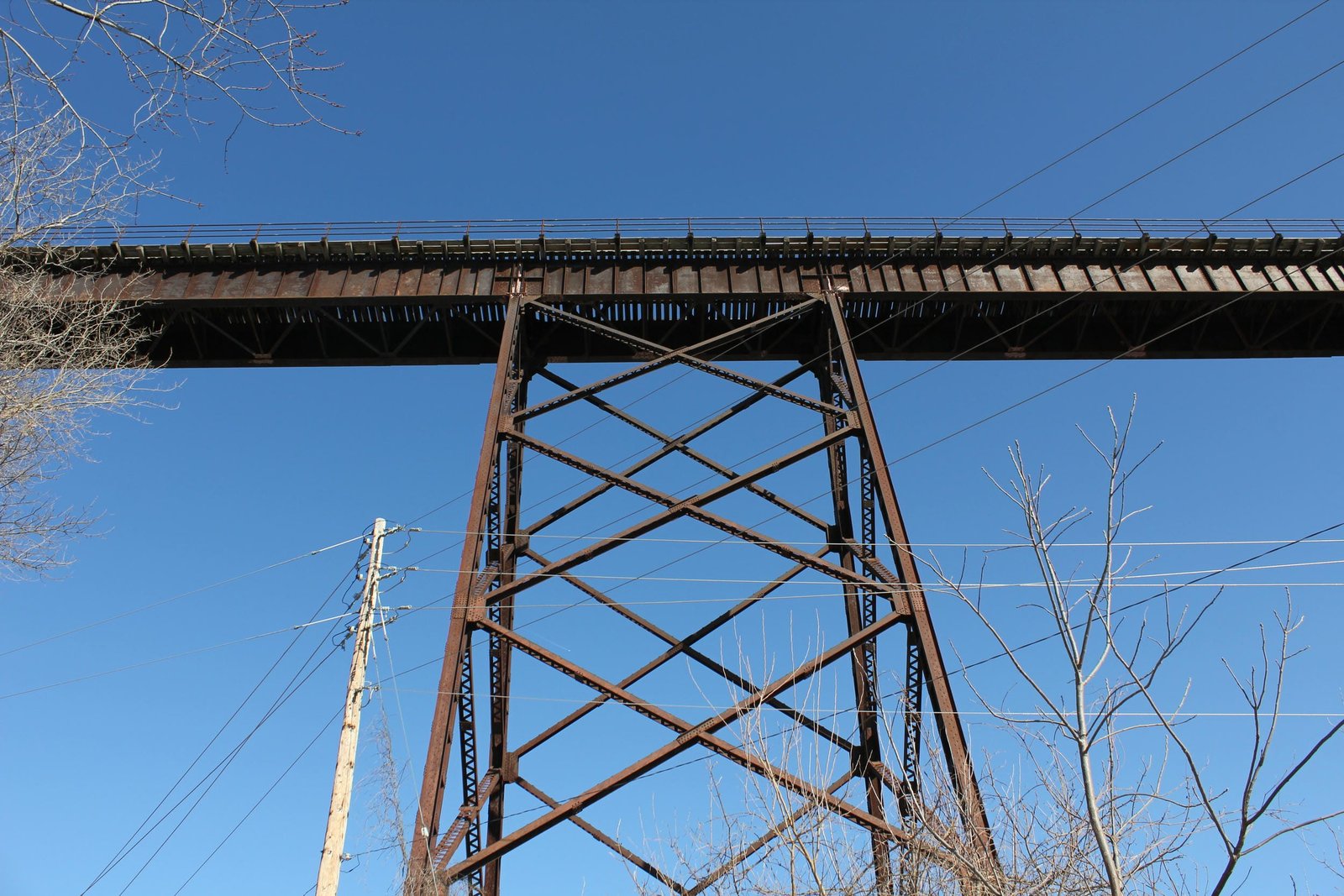
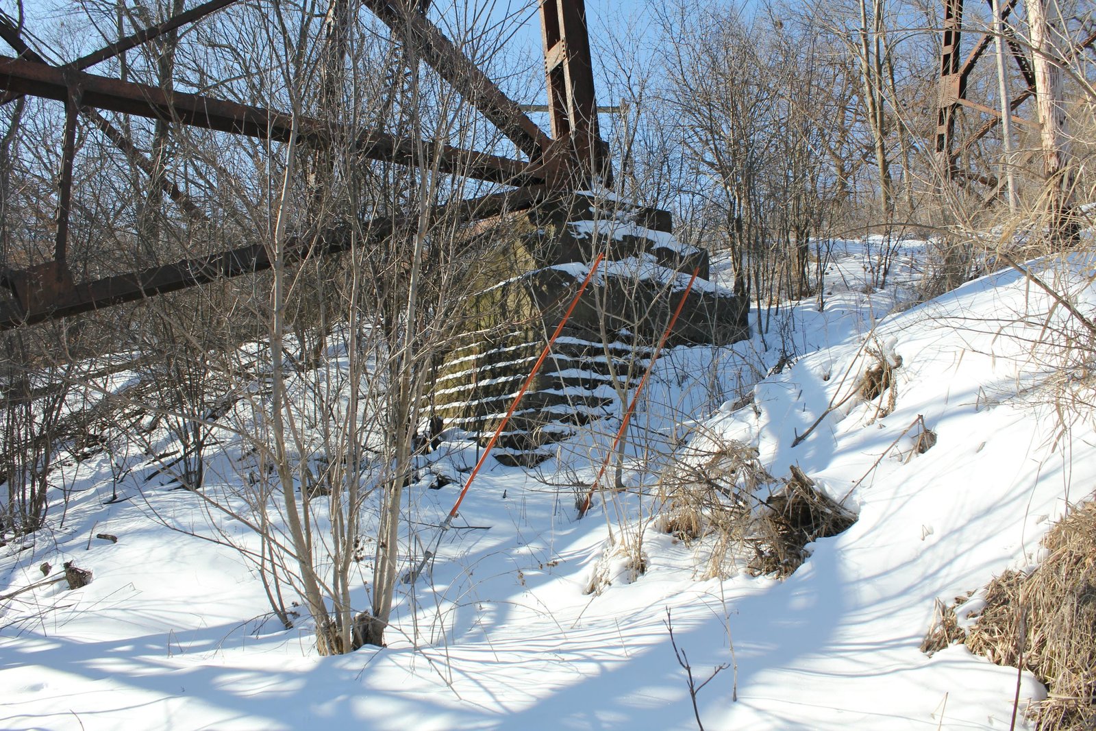
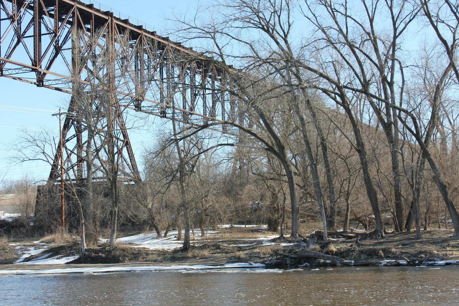
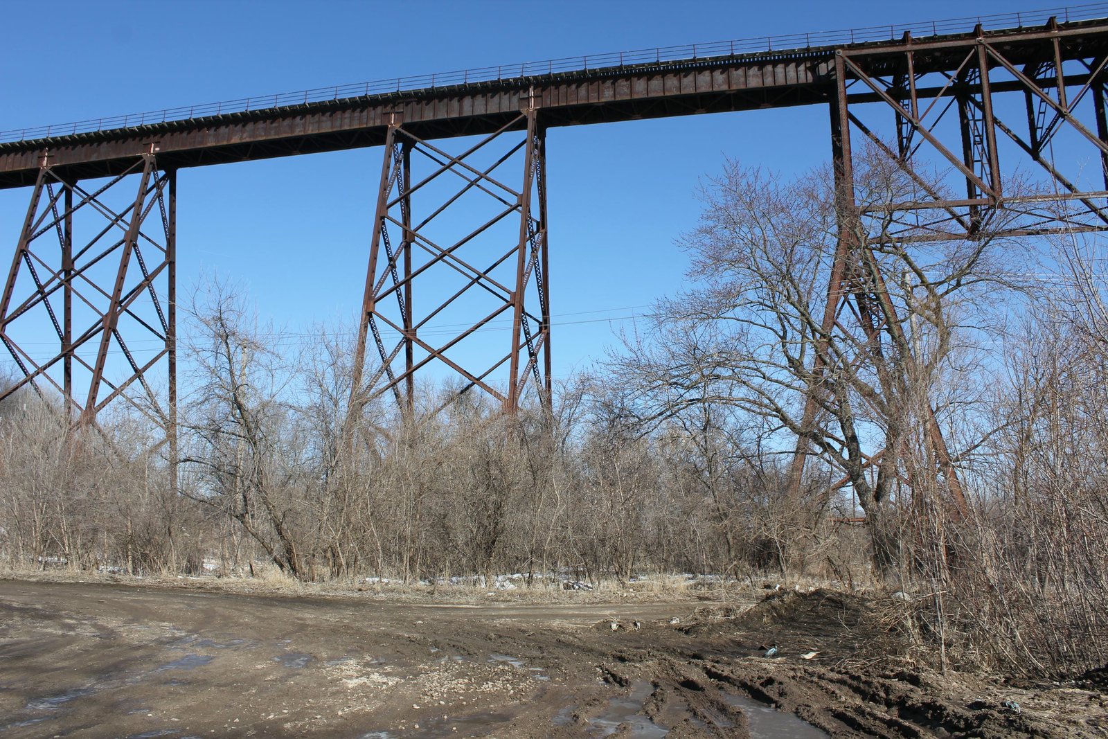
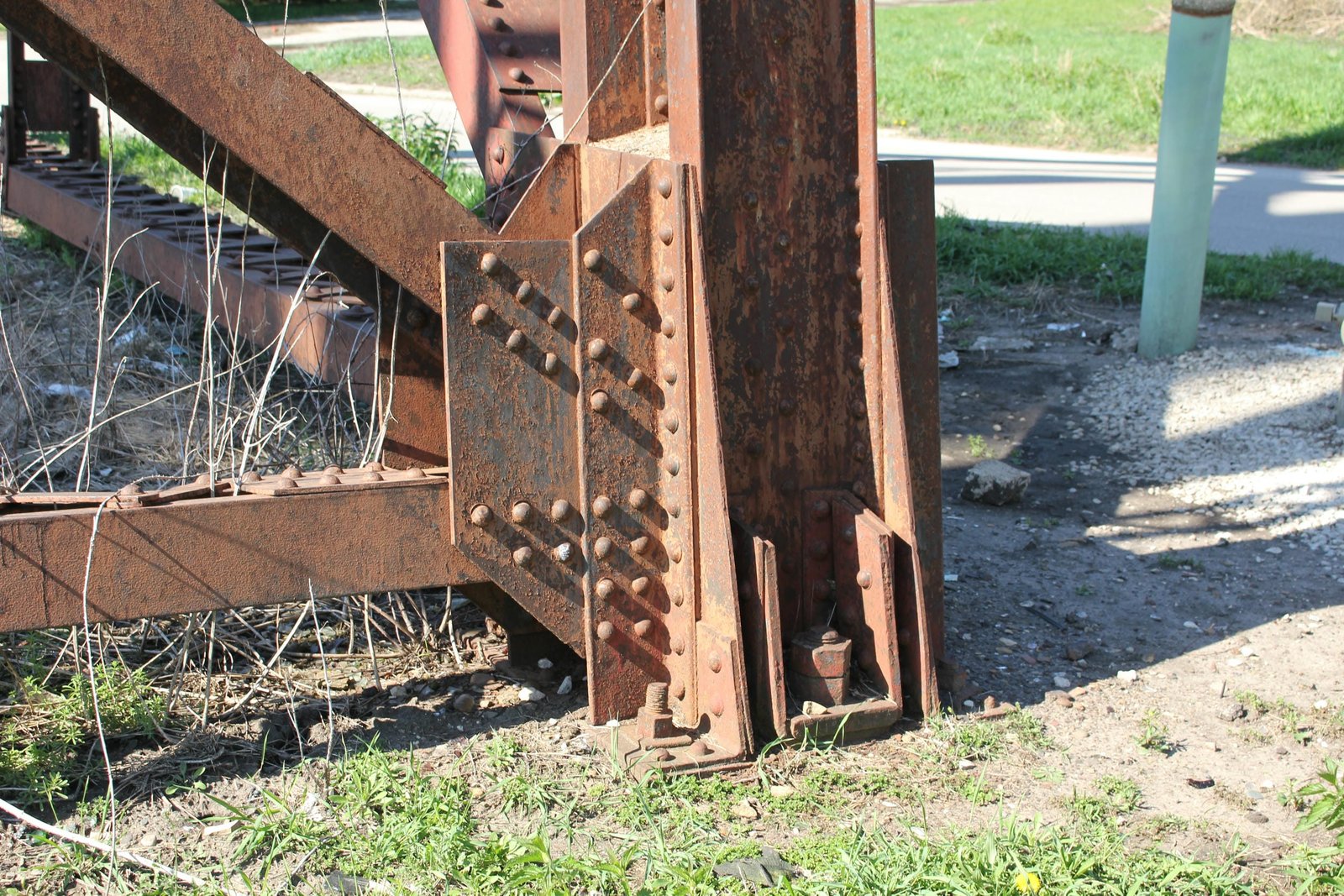
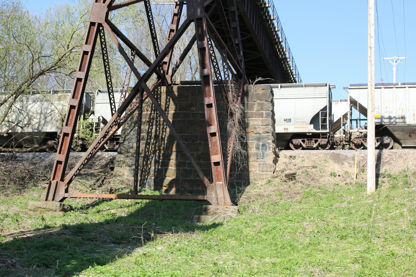
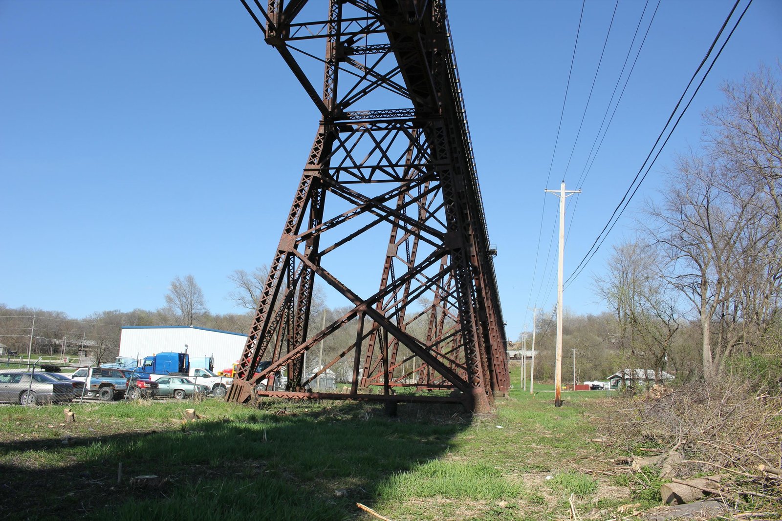
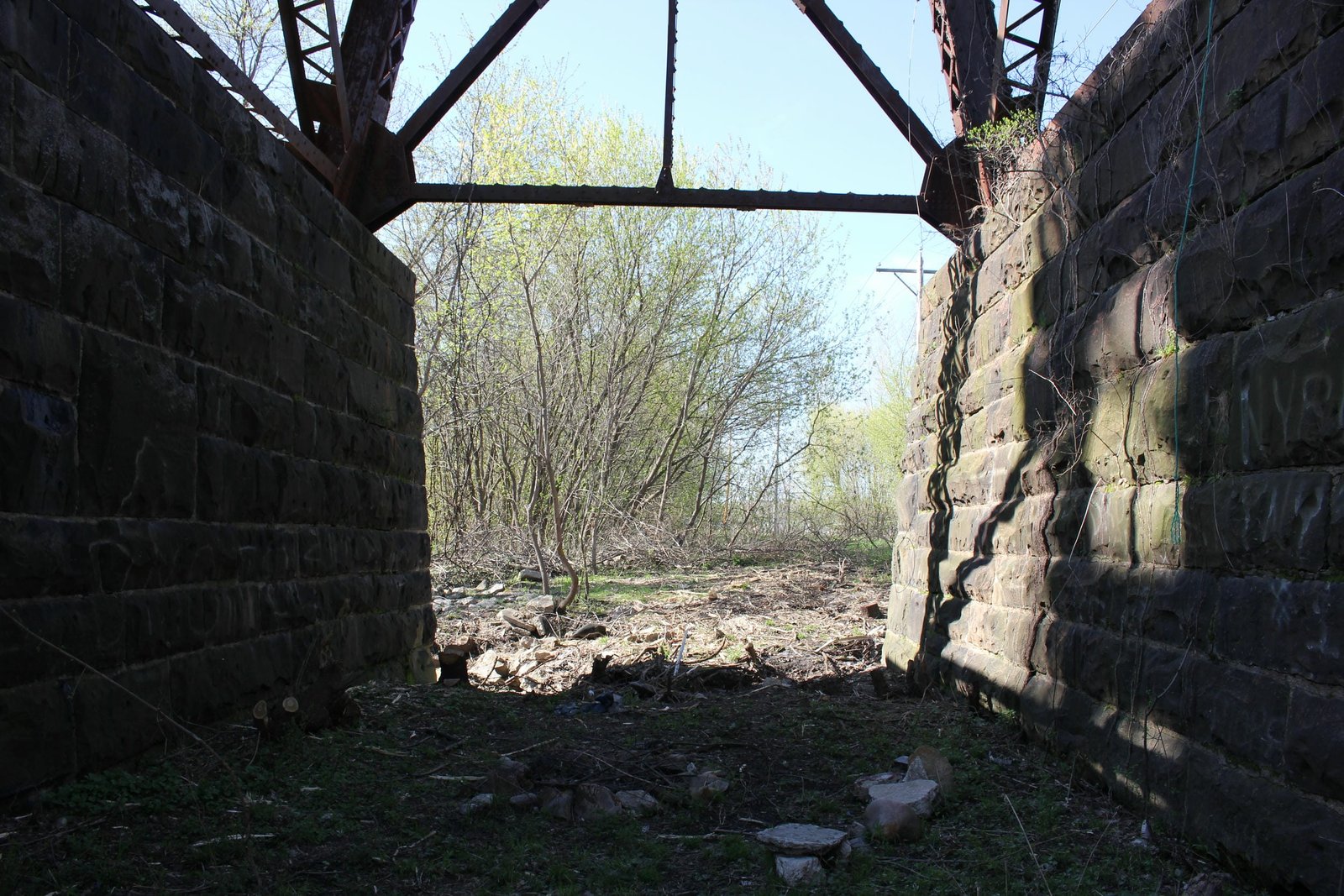
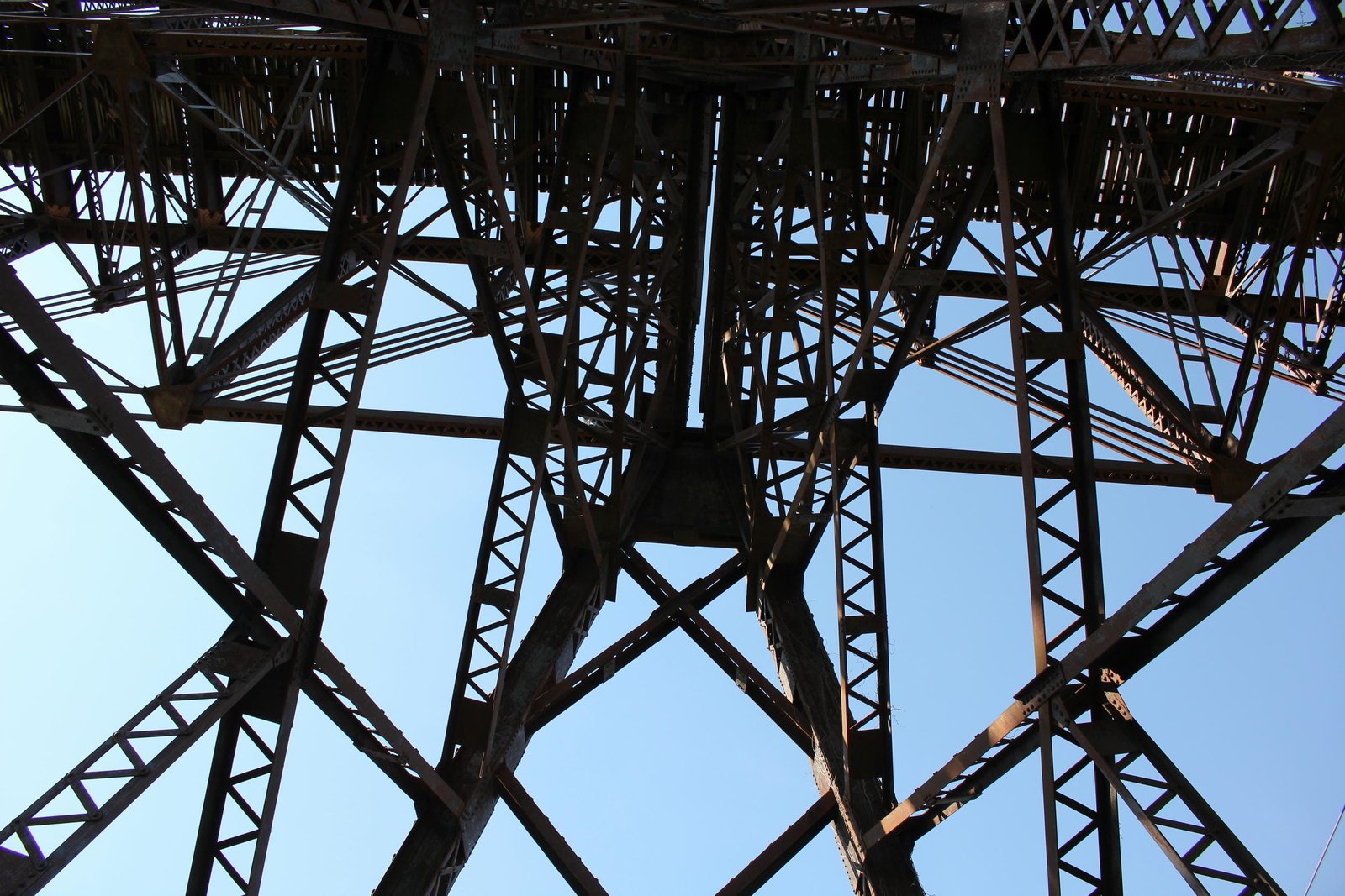
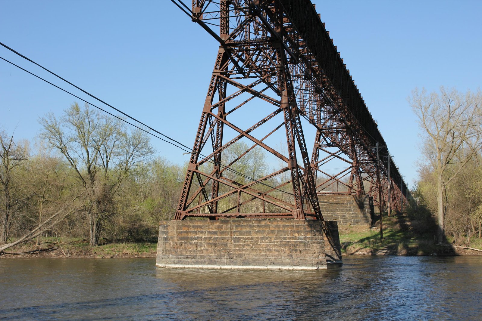
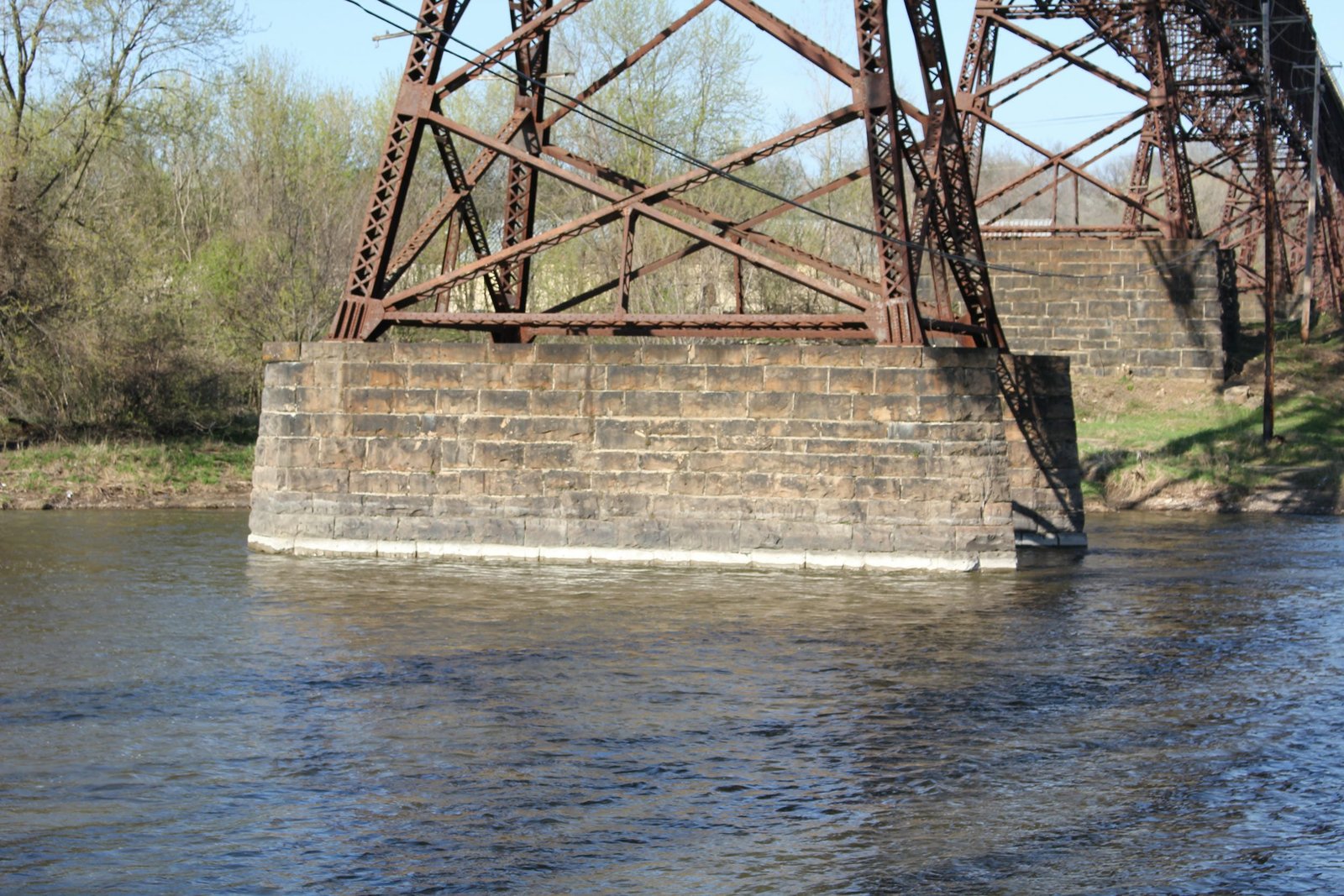
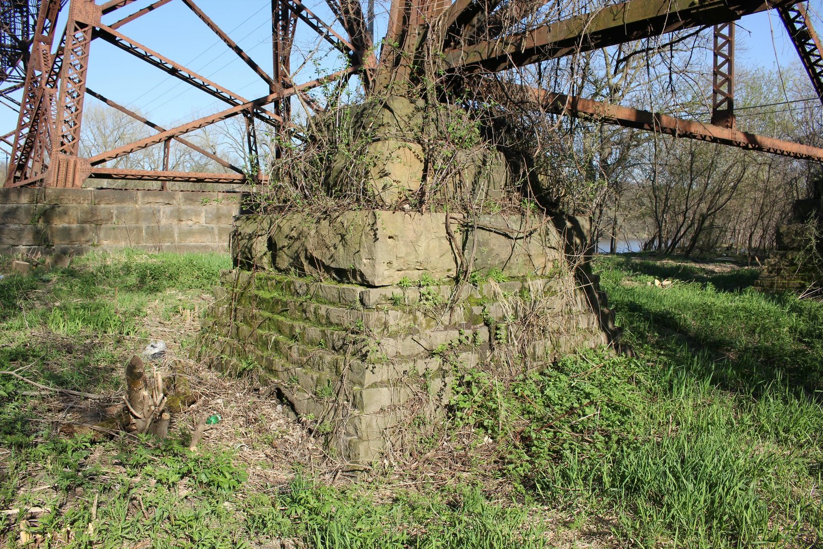
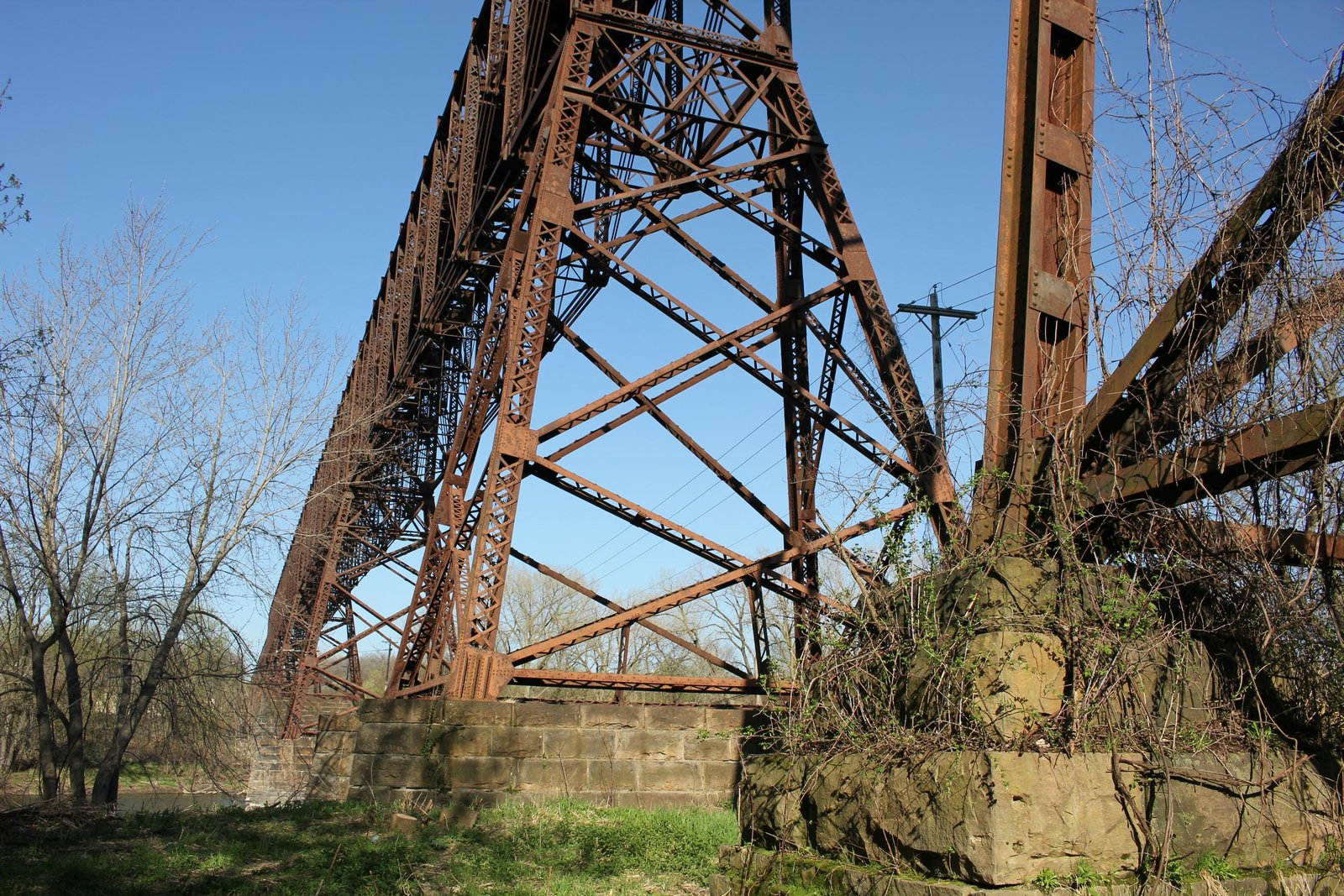
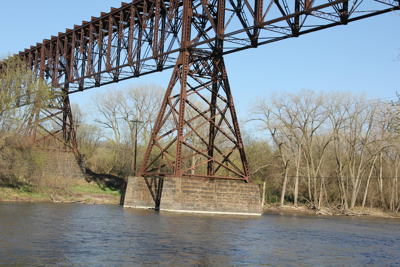
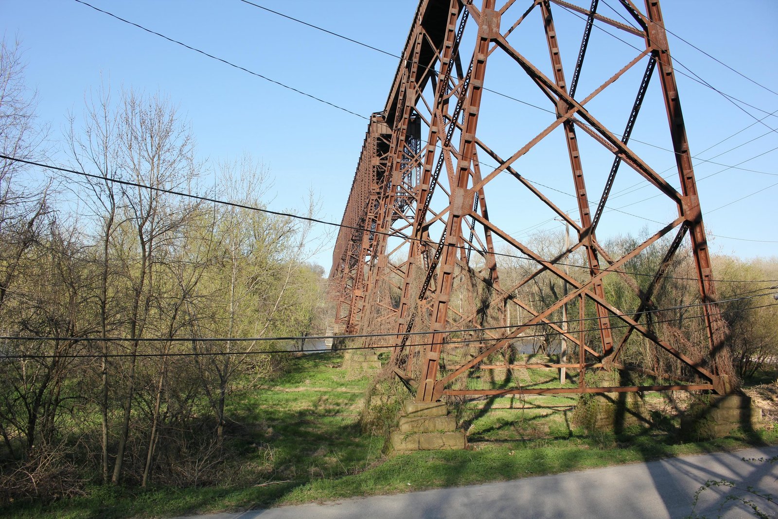
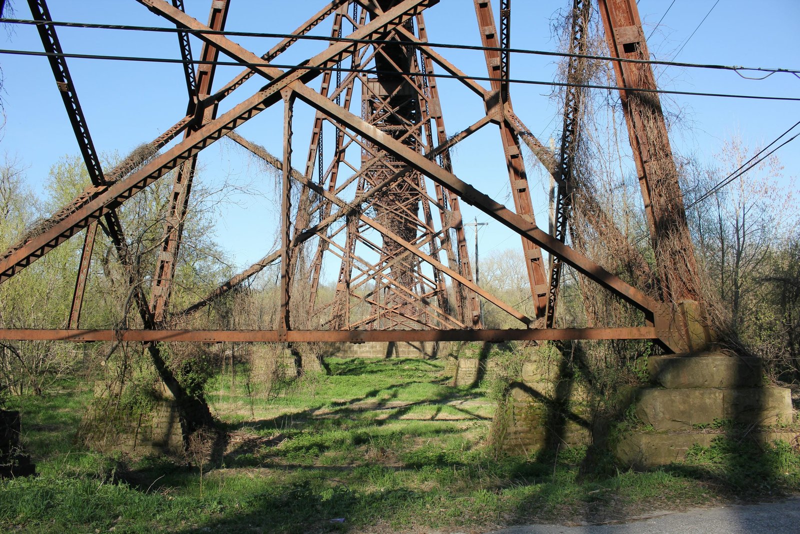
The towers supporting the truss spans (towers #10 through #14) each use a unique A-shaped design, constructed of built-up beams. These towers were designed to minimize potential uplift and allow the truss spans to freely expand and contract. The intermediate towers (towers #11, #12 and #13) are nearly identical to the end towers (towers #10 and #14), except for the weight of the material used. In addition, the towers are set onto stone piers, with the exception of tower #10 which is set onto pedestals. These towers are constructed using four heavy X-laced posts, which are set at a diagonal. At the bottom, the four beams are connected by V-laced beams. The posts on opposite sides of the track are connected two or three levels of lateral V-laced beams, with a deep lattice at the top. The posts are longitudinally connected by two or three levels of smaller V-laced beams, with a vertical beam connecting to the bottom. Thick plates at the apex of the tower allow the truss spans to be pinned to the tower. The stone piers consist of standard diamond shaped structures, which are reinforced with internal steel. The approach towers are similarly constructed, with built-up posts. These posts are composed of two U-shaped channels, joined by plates. At the bottom, the posts are connected by V-laced beams. All diagonal bracing is also composed of V-laced beams, with vertical members connecting the lower level of bracing to the bottom bracing. With the exception of towers #1 and #2, all towers are similar, with various heights set onto stone pedestals. Towers #1 and #2 use sloped bottom connections, with half of the towers set onto stone pedestals and half set onto diamond shaped stone piers. Piers were used adjacent to the former IC railroad line, due to the possibility of derailment. The stone pedestals consist of various sizes of stonework, and are generally a tapered square. All pedestals and piers are reinforced with I-beams running parallel to the viaduct and steel channels running transverse to the viaduct. The abutments use a standard rectangular shape without wing walls, and the embankment is graded around the abutments. The foundations of all substructures consist of concrete filled excavations.
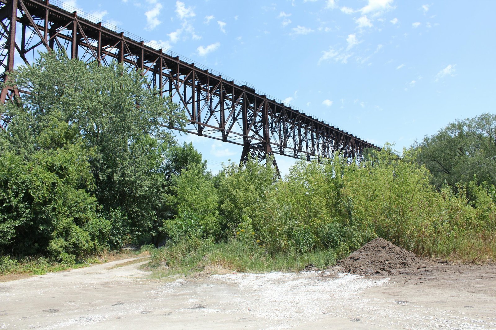
Girder viaducts on steel towers were often the most economical design for long, tall bridges crossing large valleys. While still complex to design and construct, these bridges were simpler and required less skilled construction than large masonry bridges or other steel designs. Large viaducts like this are relatively uncommon in the Midwest, as the terrain was generally flat and large embankments were avoided where possible. In Iowa, the Des Moines River between Fort Dodge and Des Moines runs through a deep valley, requiring either steep approaches or tall viaducts to cross. This bridge was the second of three notable viaducts constructed across the Des Moines River, with the Chicago & North Western Railway Boone Viaduct (Kate Shelley Bridge completed in 1901 and the Chicago, Milwaukee & St. Paul Railway (Milwaukee Road) viaduct between Madrid and Woodward completed in 1913. Of the three, the Fort Dodge Viaduct was the only single track viaduct completed during this time. In addition, it was both shorter and less tall than the Boone Viaduct; but was longer and taller than the Madrid Viaduct. The Boone Viaduct uses a similar Baltimore deck truss design with a longer main span, while the Madrid Viaduct used riveted Warren deck trusses. Today, the Boone Viaduct still stands, but has been bypassed by a new bridge. The Madrid Viaduct was replaced by a new girder bridge in the early 1970s as part of a flood control project to construct Saylorville Lake.
The Baltimore truss design was developed in the late 19th Century to allow for construction of longer pin-connected spans, without sacrificing economy or strength. While traditional Pratt spans were typically limited to approximately 200-foot lengths in extreme cases, Baltimore spans allowed for significantly longer spans to be constructed. This design remained popular throughout the early years of the 20th Century, before ultimately being superseded by other riveted truss designs. Deck plate girder spans were also popular for railroad use, as they were durable and easy to construct. Large steel towers became popular for bridges in the late 19th Century, due to the ease of construction and minimal amount of material required. Since the initial construction, the bridge has seen several alterations. It appears that additional lateral bracing and cover plates was added to the bottom of the trusses in the mid-20th Century, likely to strengthen the bridge for heavier engines. In addition, the original floorbeams and stringers were replaced with modern steel beams in approximately 2010. Today, the bridge remains in use and is a landmark to the City of Fort Dodge. Overall, the bridge appears to be in fair to good condition, and remains well maintained. The author has ranked this bridge as being nationally significant, due to the size and design of the structure.
Citations
| Builders and build date | The Engineering Record; Volume 49, Issue 6 |
| Railroad History Citation | ICC Valuation Information, Compiled by Richard S. Steele |