


Click the photo to view the full-size version
| Name | UP Buffalo Lake Bridge Chicago & North Western Railway Bridge #2655 |
| Built By | Milwaukee, Sparta & North Western Railway |
| Currently Owned By | Union Pacific Railroad |
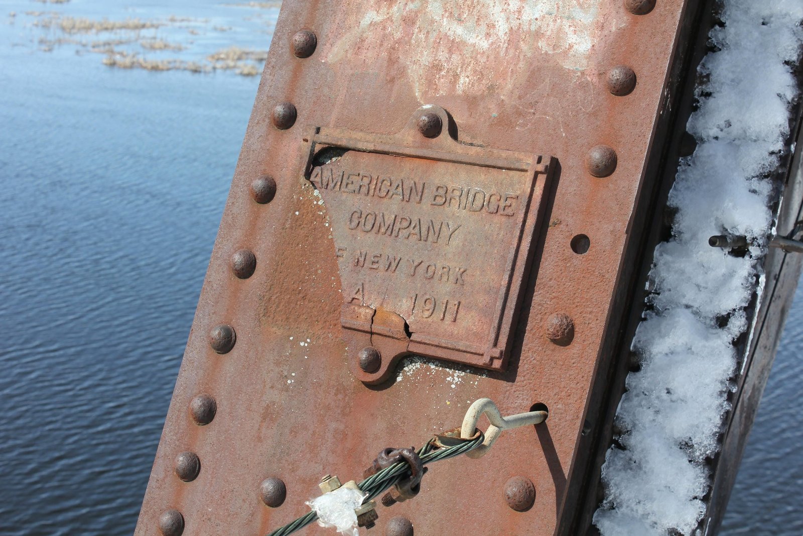
| Superstructure Contractor | American Bridge Company of Chicago, Illinois (Truss Span) Pennsylvania Steel Company of Steelton, Pennsylvania (Girder Spans) |
| Substructure Contractor | Bates & Rogers Construction Company of Chicago, Illinois |
| Length | 1,006 Feet Total, 206 Foot Main Span |
| Width | 1 Track (Main Span and Substructures Built For 2) |
| Height Above Ground | 25 Feet (Estimated) |
| Superstructure Design | Quadrangular Lattice Through Truss Swing Span and Deck Plate Girder |
| Substructure Design | Concrete, Steel Tower and Steel Cylinder |
| Date Built | 1911 |
| Traffic Count | 5 Trains/Day (Estimated) |
| Current Status | In Use |
| Chicago & North Western Railway Bridge Number | 2655 |
| Union Pacific Railroad Bridge Number | 225.45 |
| Significance | High Significance |
| Documentation Date | 3/25/2016 |
In 1884, the Princeton & Western Railway (P&W) constructed a 13 mile branch from the existing Chicago, St. Paul, Minneapolis & Omaha Railway (Omaha Road) at Wyeville, Wisconsin to Necedah, Wisconsin. The railroad soon came under lease of the Chicago & North Western Railway (C&NW). During the early 20th Century, the C&NW began a program of improvements, constructing new cutoffs and significantly increasingly efficiency over the system, particularly in Wisconsin and northern Illinois. In 1910, the Milwaukee, Sparta & North Western Railway (MS&NW), a subsidiary of the C&NW, began construction a new cutoff across central Wisconsin. In 1912, the MS&NW completed 23 miles between Sparta, Wisconsin and Wyeville, Wisconsin; as well as 133 miles between Necedah and Wiscona, a railroad junction on the north side of Milwaukee. The P&W was sold to the MS&NW in 1912, which was promptly consolidated into the C&NW. This line provided a better connection for the C&NW through Wisconsin, and avoided the steep grades of the previous mainline from Sparta to Madison. The line also improved the C&NW connection to the Twin Cities of Minneapolis and St. Paul by way of the C&NW controlled Omaha Road. The line between Butler, Wisconsin and Clyman Junction, Wisconsin would be double tracked; while the remainder between Clyman Junction and Wyeville was built wide enough for a second track, but no second track was installed.
By the 1920s, the C&NW was operating an expansive railroad network throughout the Midwest, radiating north and west from Chicago. This line served as one of the principal mainlines of the railroad, connecting Milwaukee to the Twin Cities. In 1959, much of the second track between Butler and Clyman Junction was removed as operations over the line no longer warranted a second track. The line remained largely unchanged until March 1973, when a tunnel collapsed at Tunnel City, Wisconsin. This led to the line being abandoned west of Tunnel City, and a new connection track being constructed to the Chicago, Milwaukee, St. Paul & Pacific Railroad (Milwaukee Road) mainline, which the C&NW would use to reach Winona, Minnesota. In 1995, the C&NW was purchased by the Union Pacific Railroad, the current owner of this line. Today, UP operates the Wyeville Subdivision between Wyeville and Adams, Wisconsin; the Adams Subdivision between Adams and Wiscona; and the Winona Subdivision between Wyeville and Tunnel City. The segment between Tunnel City and Sparta remains abandoned, although much of the infrastructure remains intact.
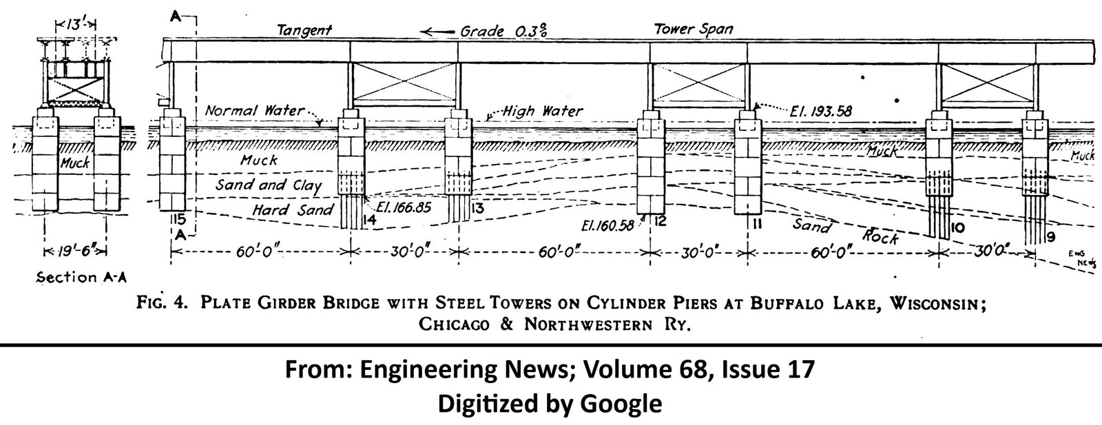
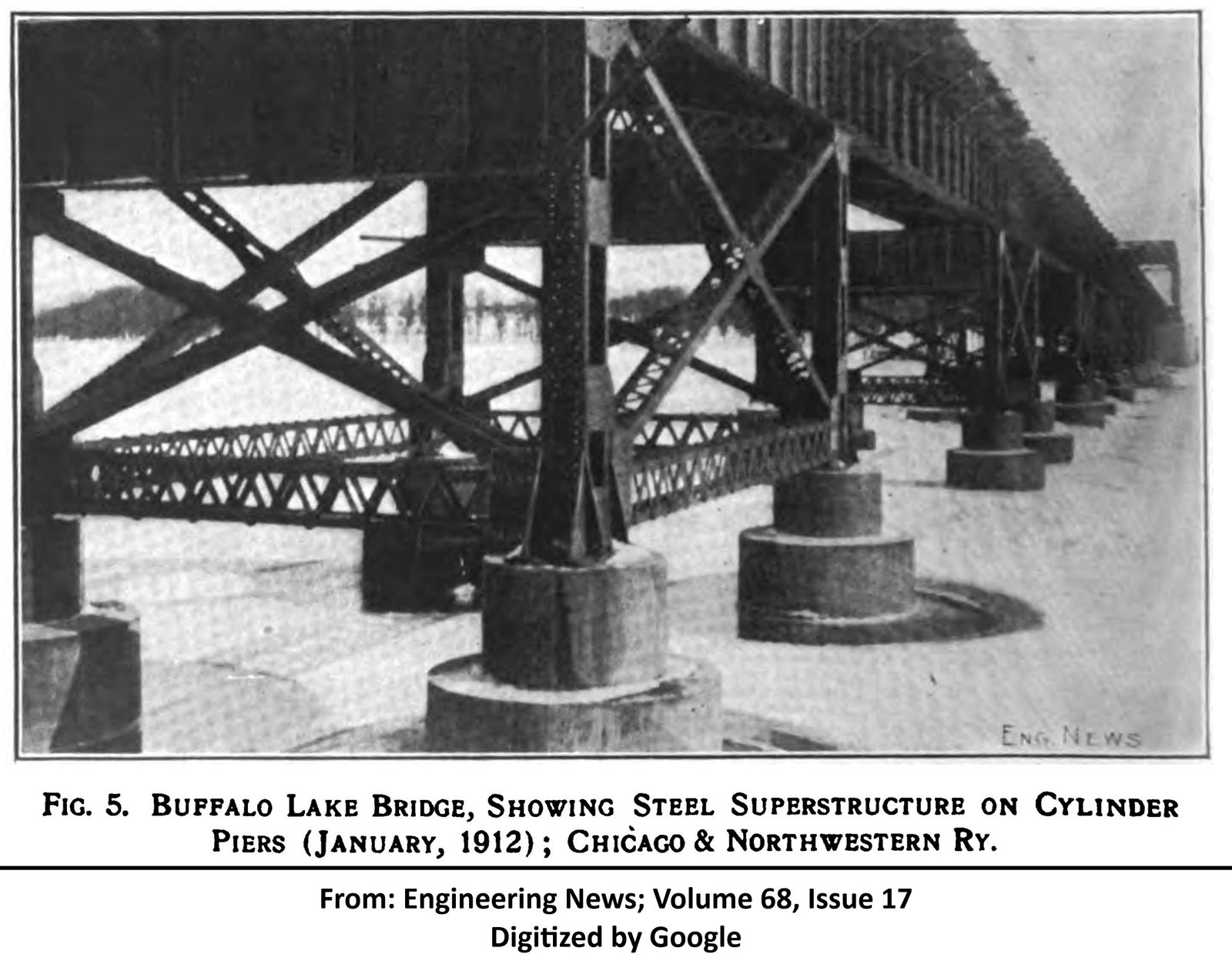
View an article discussing the use of cylinder piers on this bridge (digitalized by Google)
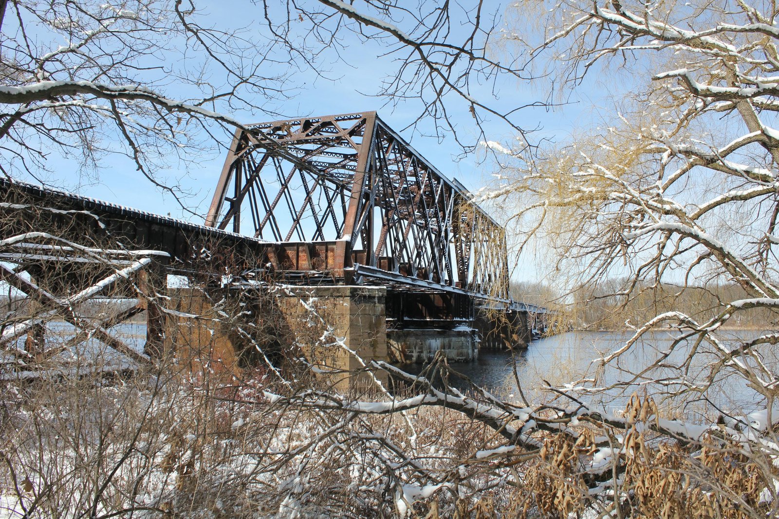
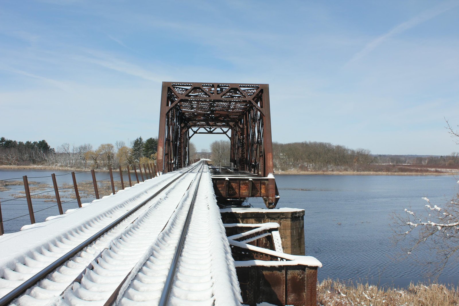
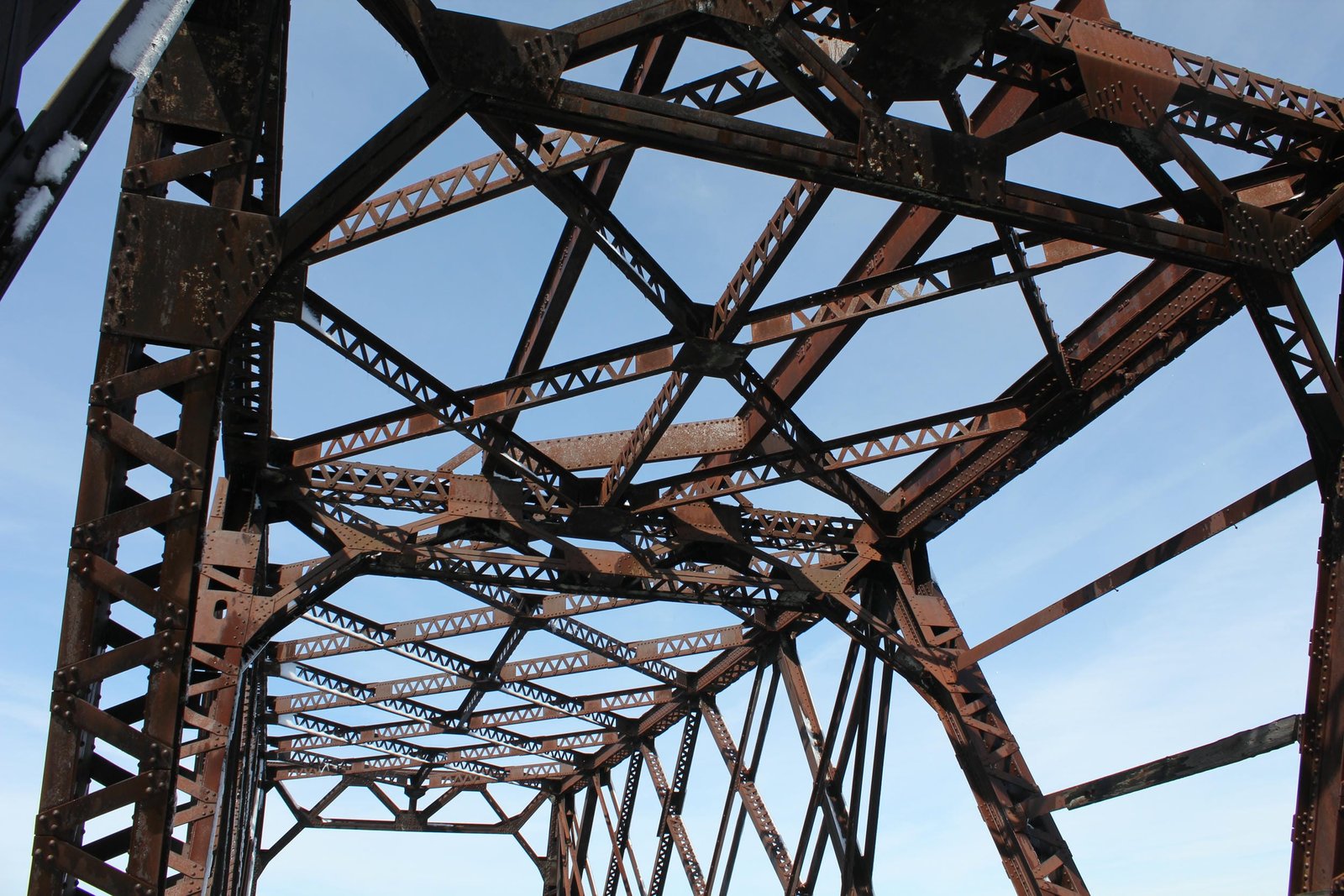
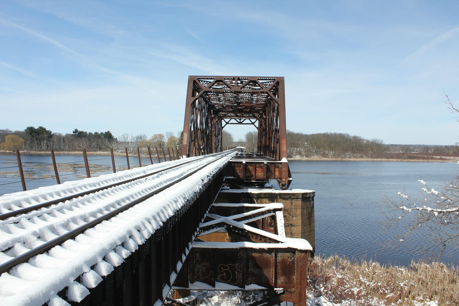
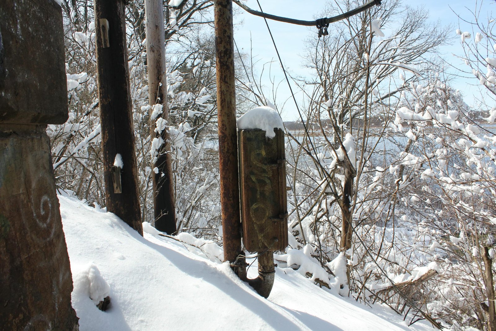
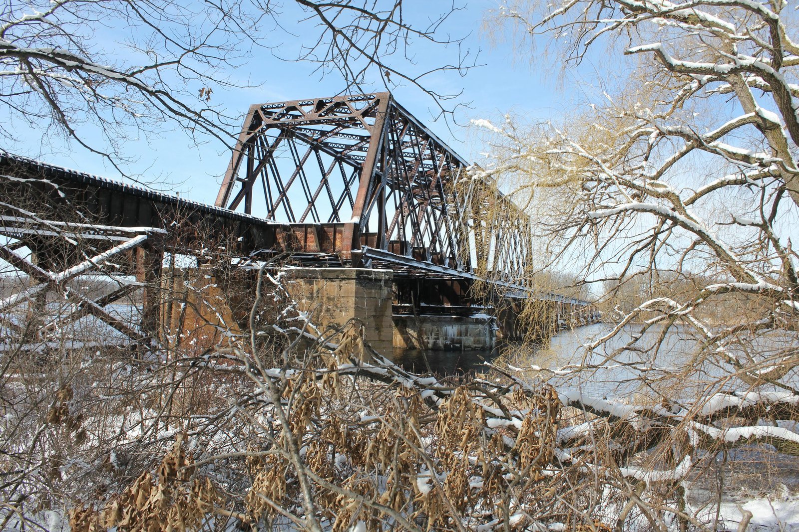
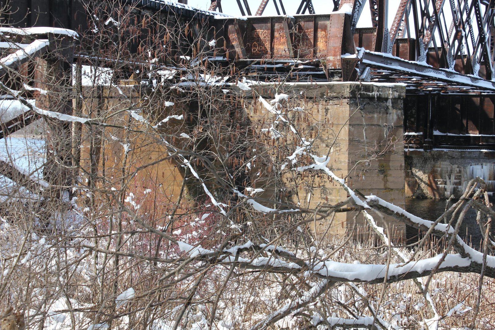
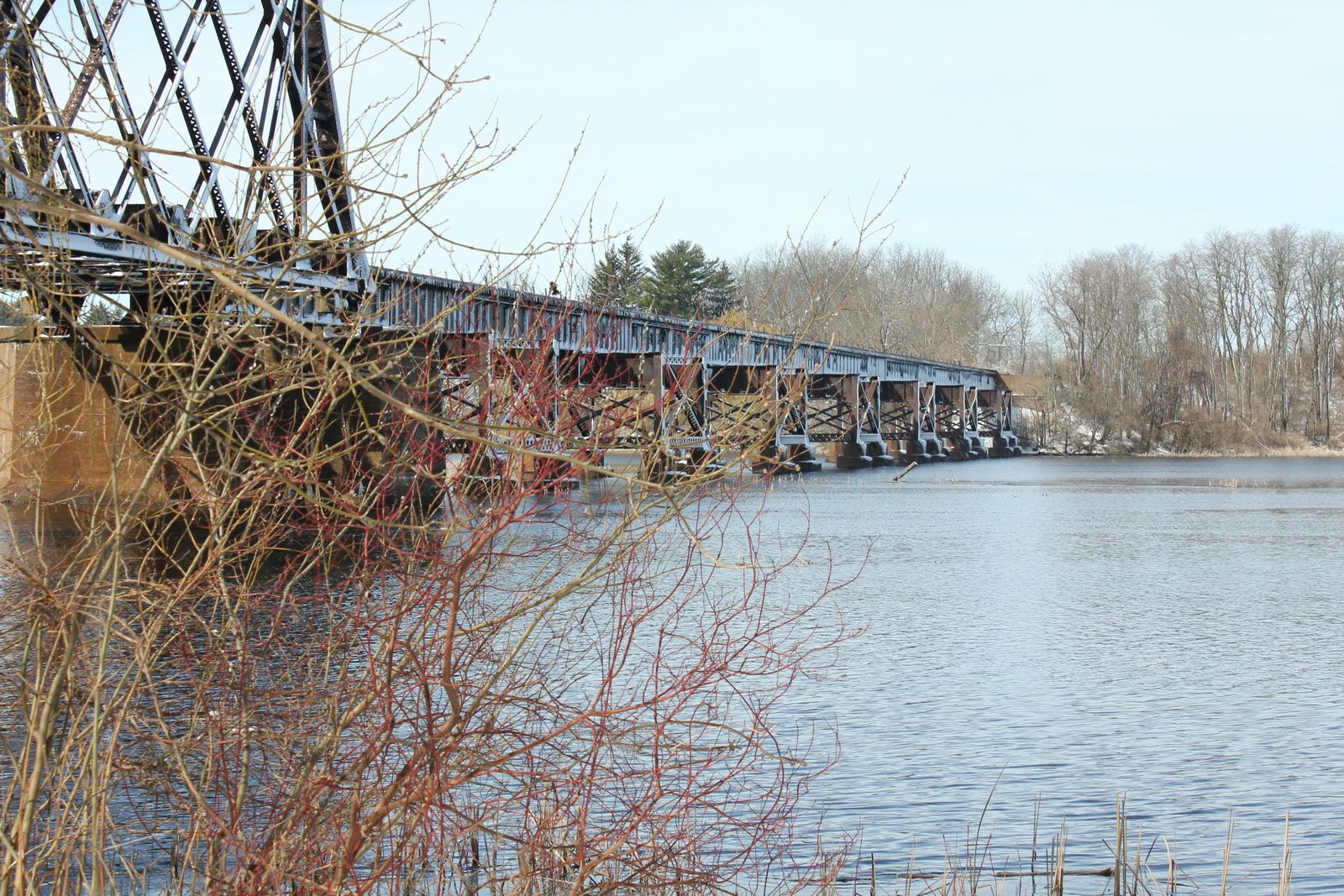
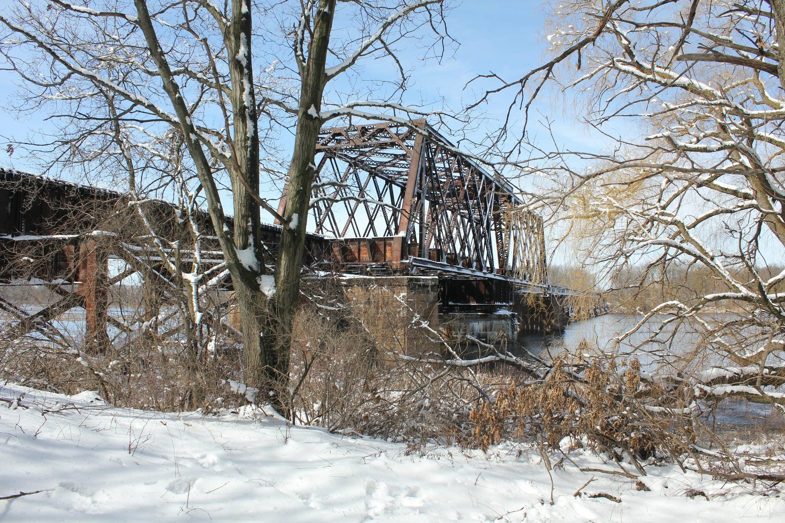
Located south of Packwaukee, this unique through truss swing bridge carries the former Chicago & North Western Railway mainline over Buffalo Lake (Fox River). Built in 1911 as subsidiary Milwaukee, Sparta & North Western Railway constructed a new line across central Wisconsin, this bridge was the largest structure on the new line, requiring a movable span as the Fox River was still considered navigable when this bridge was constructed. The bridge consists of a large 206-foot, riveted quadrangular lattice through truss swing span, approached by two 40-foot and one 30-foot deck plate girder spans on the east end and eight 60-foot and seven 30-foot deck plate girder spans on the west end. The bridge is set onto concrete piers and abutments with steel cylinder piers and steel towers carrying the approach spans. As traffic over this line was anticipated to grow in the 20th Century, the swing span and substructures were constructed for two tracks, and the bridge could have easily been double tracked by adding additional deck girder spans to the north side of the structure. American Bridge Company fabricated the swing span, while the Pennsylvania Steel Company fabricated the approach spans. Bates & Rogers Construction Company, which set up a temporary headquarters nearby, constructed the substructures. It is unknown how long the swing span was operational, but electric service boxes indicate that the bridge was motorized with an electric engine.
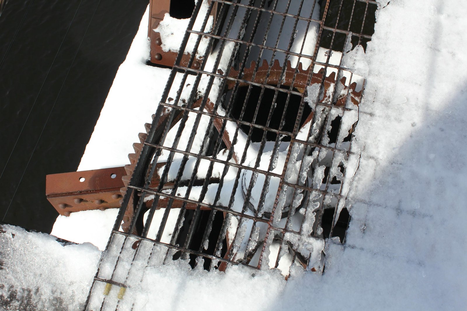
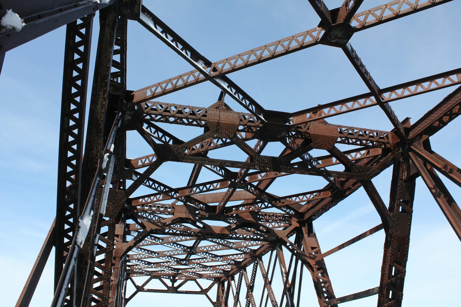
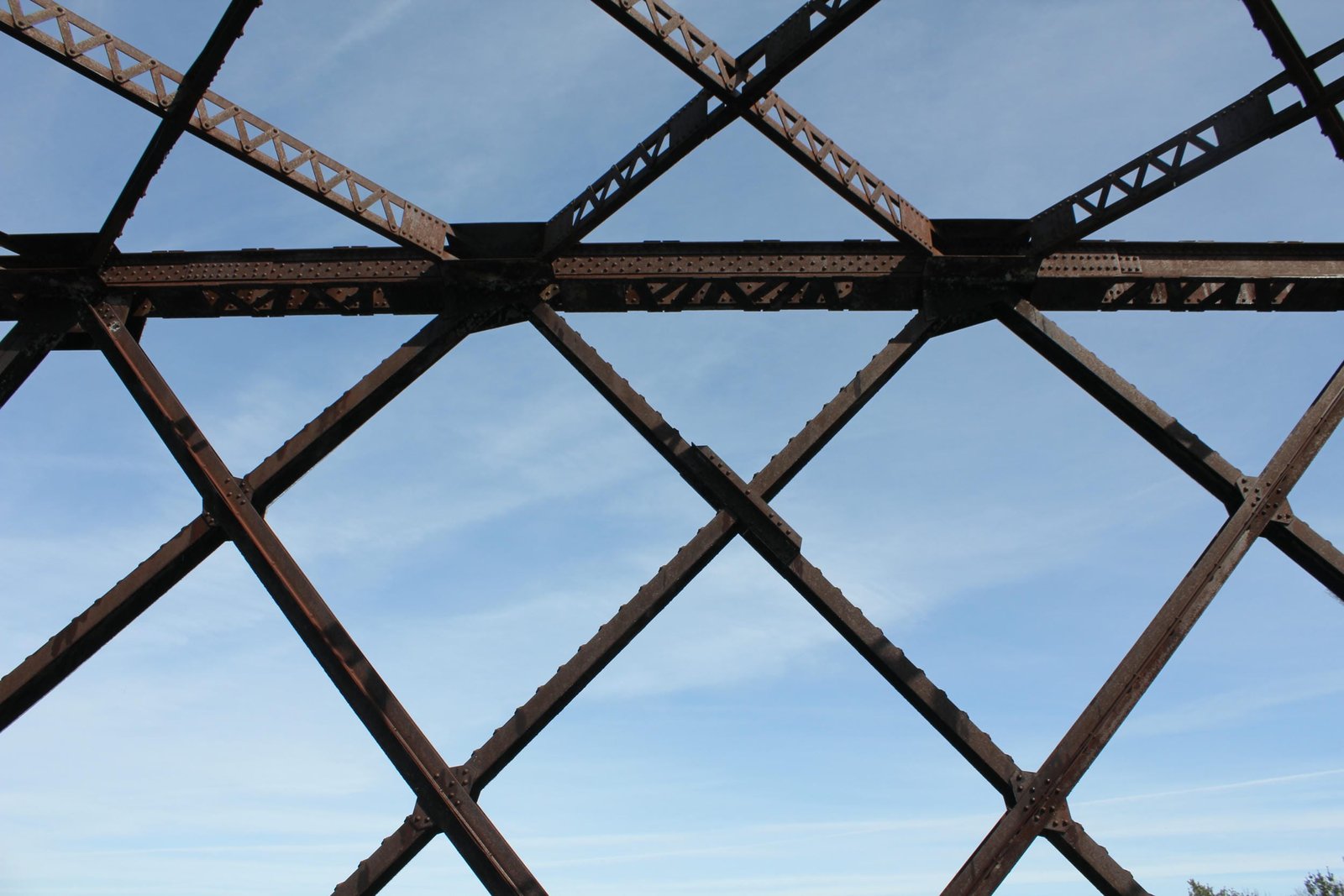
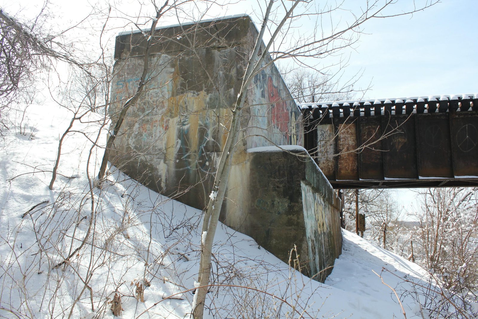
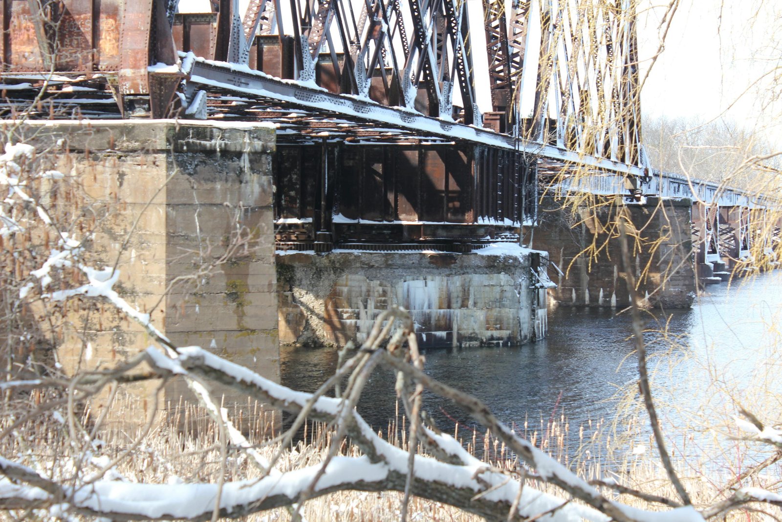
The swing span use a modified version of a standard 20th Century quadrangular lattice through truss span, with heavy built-up members and a standard floor. The top and bottom chords consist of built-up beams, which are constructed using X-lacing on the bottoms and V-lacing on the top. Many of the diagonal members are constructed using built-up beams with tight V-lacing, while other diagonal members use an "L" shaped bar. The endposts use a traditional design, with heavy V-laced members covered by a solid plate on the outside. The interior of the span uses an unusual triangular design, consisting of massive built-up beams. The top of the center portion of the bridge uses four large rolled beams laid longitudinally, and a machinery house was once located in the center of the span. Typical of spans from this era, the portals consist of a heavy M-frame portal bracing, which is constructed exclusively of built-up V-laced members. The upper lateral bracing also uses a V-laced beam design, and an additional longitudinal built-up beam has been placed in the center to provide greater stability. The floor is composed of heavy plate girder floorbeams and stringers, with two stringers placed per track. Typical of swing spans constructed in this era, the main span uses a rim-bearing design, where the superstructure is set onto a large square steel drum constructed of plate girders. This drum is turned along a set rollers by a system of gears. While significant portions of the turning mechanism have been removed, several of the gears remain intact. While the original rollers at the end appear to be intact, the bridge has been permanently fixed in the closed position, and has likely not operated since the early 20th Century. The main three piers are constructed of concrete, and use a typical design. Similar to other 20th Century swing spans, the center pier is constructed using an octagonal shape instead of a square or circular shape.
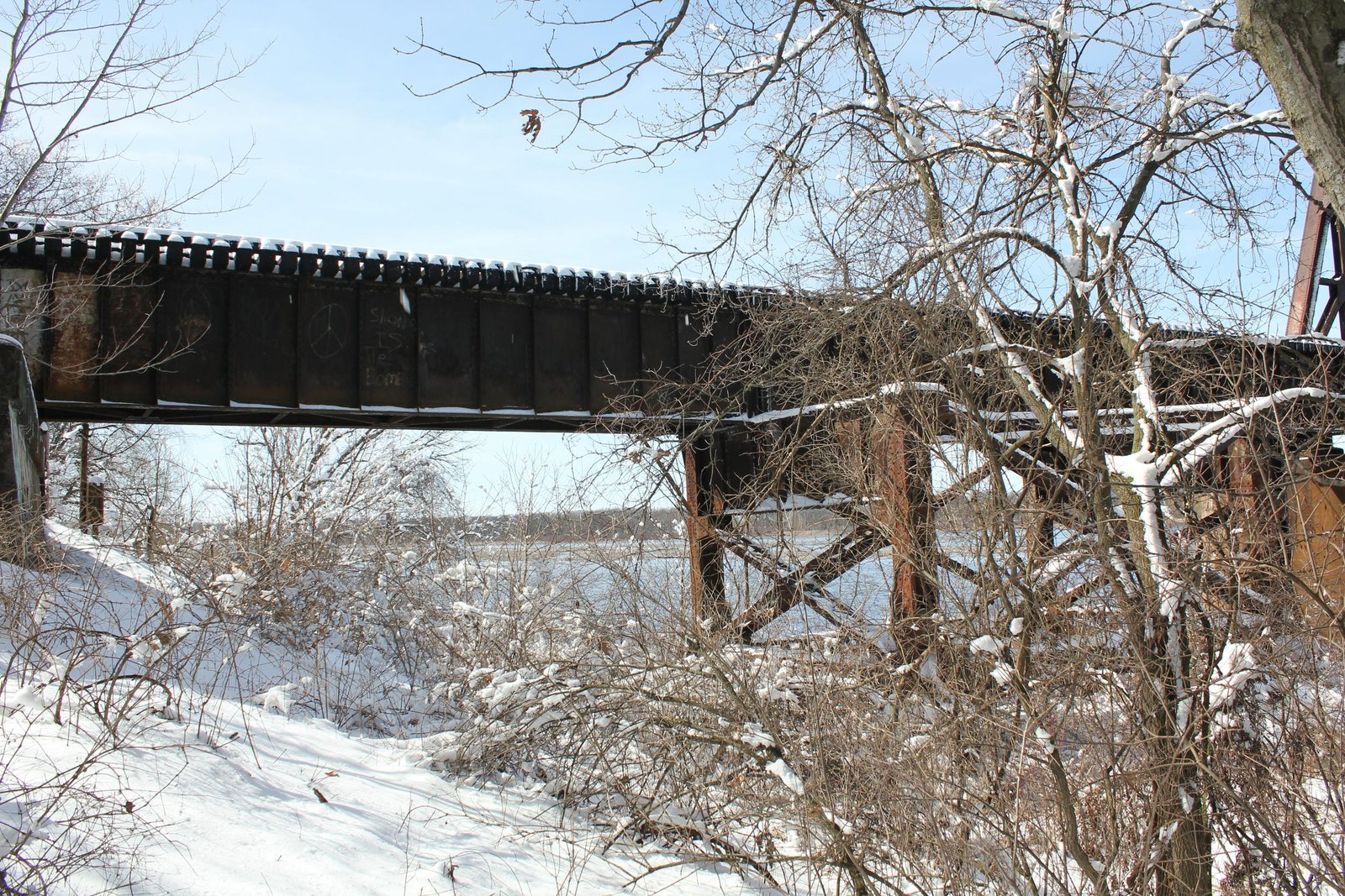
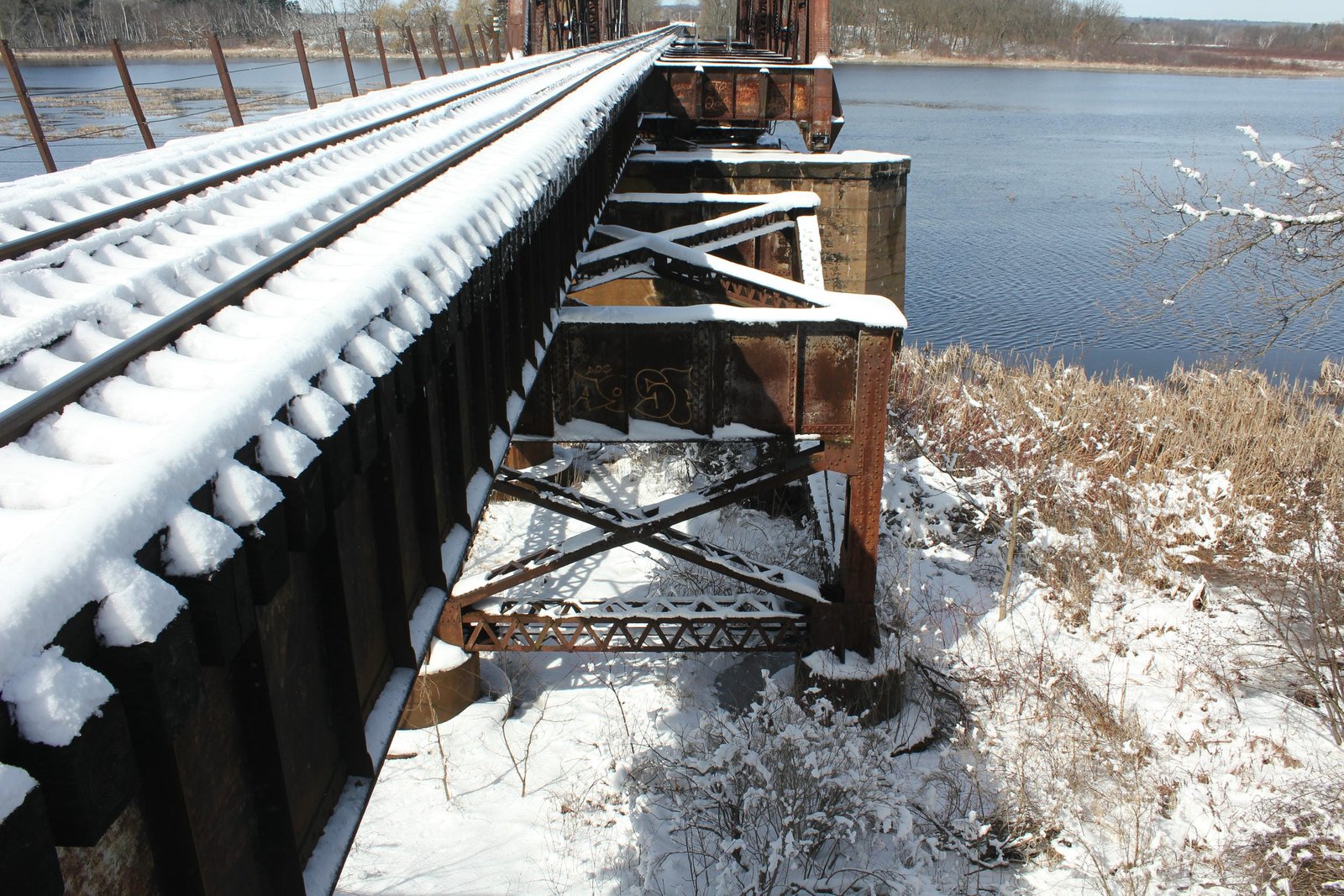
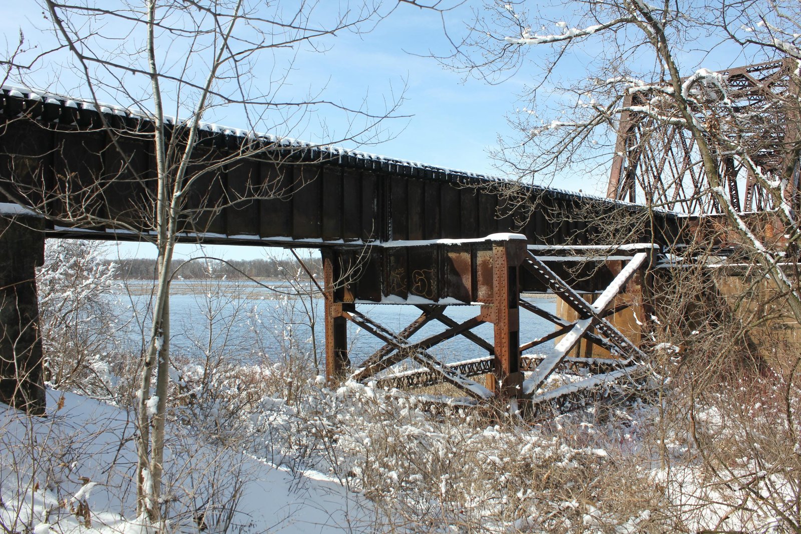
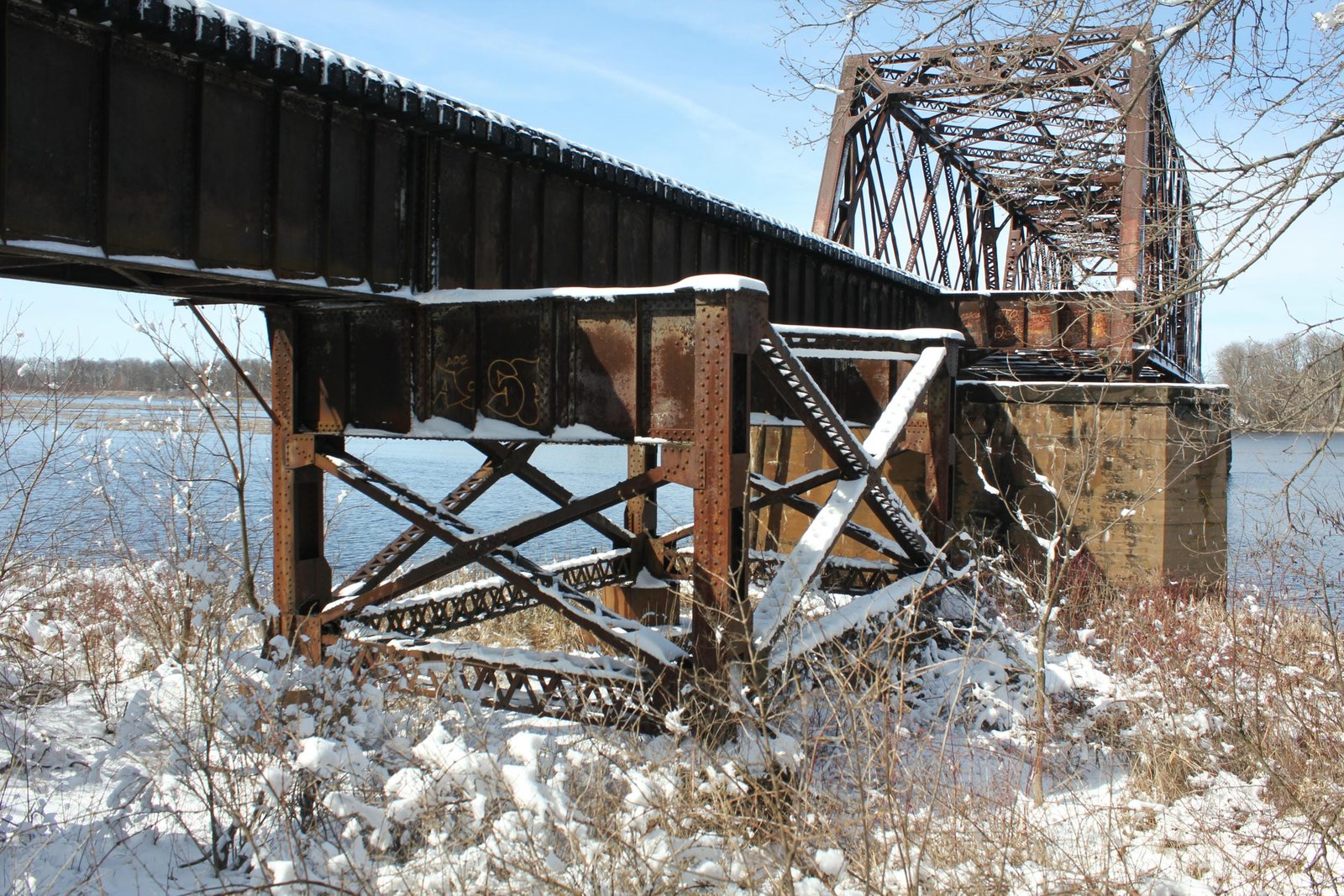
The approach spans are also constructed using an innovative design. The superstructure is constructed of traditionally composed deck plate girders, with heavy girders and an open deck. The intermediate spans use 40-foot and 60-foot spans, while the towers are crossed by 30-foot spans. The towers themselves are constructed of two bents, which are connected a transverse plate girder on top and a transverse strut on the bottom. These bents are connected by a longitudinal strut on the bottom and diagonal bracing forming an "X" shape. With the exception of the plate girders, all components of the towers are composed of V-lacing of various thicknesses and spacing. Unlike the nearby bridge across Oxford Millpond, the girders are set directly onto the towers instead of onto hangers on the transverse girder. The towers are founded on steel cylinders, which are comprised of an 8-foot diameter lower cylinder and a 5-foot diameter upper cylinder. These cylinders are founded on 6-inch diameter steel shells, which are sunk to hard sand or rock; and the entire cylinder is filled with concrete. The abutments use a standard square design, and do not contain wing walls. Cylinder piers became popular with the C&NW in the early 20th Century, as they were strong and relatively easy to construct.
This type of truss design is relatively uncommon throughout the United States, and even more uncommon for use in a movable span. However, a few railroads preferred the design, such as the Chicago, Rock Island & Pacific Railway (Rock Island), the Chicago & North Western Railway (C&NW) and the Omaha Road. Spans constructed in the late 1870s and early 1880s for the C&NW featured an arched and pedimented lattice portal bracing, light sway bracing and laced members. The second generation was nearly exclusively constructed by Lassig Bridge & Iron Works between 1884 and 1900, and featured heavier members and a pedimented portal bracing. While the design fell out of favor for the Rock Island and Omaha Road around the turn of the 20th Century, the design remained popular with the C&NW into the 1920s. 19th Century versions of this design were primarily constructed out of iron, while 20th Century versions of this design used much heavier members and were constructed of steel. The C&NW preferred this design, as it was both strong and demonstrated great resilience in case of a derailment. The span of this bridge is exceptionally large for this design, and is among the heaviest quadrangular lattice through truss spans constructed for the C&NW. Since the initial construction, the bridge has seen few alterations, and remains in service. Overall, the bridge appears to be in fair to good condition, with no significant deterioration noted. The author has ranked this bridge as being highly significant, due to the movable truss design and innovative construction techniques.
Citations
| Builder and build dates | Chicago & North Western Railway Valuation Notes at the Chicago & North Western Historical Society Archives |
| Railroad History Citation | ICC Valuation Information, Compiled by Richard S. Steele |